How do you calculate the required heat exchanger size?
For a preliminary heat exchanger calculation, two questions usually come first:
How much heat needs to be transferred?
How much heat transfer area is required?
The basic calculations are straightforward, but selecting an actual heat exchanger requires more than putting numbers into a single formula.
A practical heat exchanger sizing calculation should consider:
- Heat duty
- Flow rate
- Inlet and outlet temperatures
- Specific heat
- LMTD
- Overall heat transfer coefficient
- Heat transfer area
- Pressure drop
- Fouling
- Fluid properties
- Operating pressure and temperature
- Material compatibility
This guide explains how to calculate the heat duty and required heat transfer area, with a practical example for a liquid-to-liquid heat exchanger.
1. Heat Exchanger Heat Duty Calculation
The first calculation is the required heat duty.
For a single-phase fluid with a known mass flow rate:
Q = ṁ × Cp × ΔT
Where:
- Q = heat duty, W
- ṁ = mass flow rate, kg/s
- Cp = specific heat capacity, J/kg·K
- ΔT = fluid temperature change, K
For a flow-through heat exchanger, the same principle can be applied to either side.
For example:
Hot water flow: 10 kg/s
Hot water inlet: 80°C
Hot water outlet: 60°C
Assume:
Cp = 4.18 kJ/kg·K
Then:
Q = 10 × 4.18 × (80 − 60)
Q = 836 kW
Therefore, the approximate heat duty is:
836 kW
The cold side should theoretically absorb approximately the same heat, ignoring heat losses:
Qhot ≈ Qcold
This heat-balance check is one of the simplest ways to identify incorrect input data.
Alfa Laval’s published heat exchanger calculation method uses the same basic relationship between heat load, mass flow rate, specific heat and temperature change.
2. Heat Duty Calculation From Volumetric Flow Rate
Many customers do not have mass flow rate.
They have:
m³/h
or:
GPM
In that case, convert volumetric flow to mass flow.
The relationship is:
ṁ = ρ × V
Where:
- ṁ = mass flow rate
- ρ = fluid density
- V = volumetric flow rate
For water, density is approximately:
1,000 kg/m³
at typical ambient conditions.
For example:
Water flow = 36 m³/h
Convert to kg/s:
36 × 1,000 ÷ 3,600 = 10 kg/s
If water is cooled from 80°C to 60°C:
Q = 10 × 4.18 × 20
Q = 836 kW
The actual density and specific heat should be used when the fluid is not water.
This is especially important for:
- Glycol
- Thermal oil
- Brine
- Refrigerants
- Chemical solutions
- High-viscosity fluids
Using water properties for another fluid can produce a misleading heat duty calculation.
3. The Four Temperatures Required for Heat Exchanger Sizing
A heat exchanger calculation normally requires four temperatures:
Hot Side
T₁ = Hot-side inlet
T₂ = Hot-side outlet
Cold Side
T₃ = Cold-side inlet
T₄ = Cold-side outlet
For example:
| Parameter | Hot Side | Cold Side |
|---|---|---|
| Inlet temperature | 80°C | 25°C |
| Outlet temperature | 60°C | 45°C |
| Flow rate | 10 kg/s | 10 kg/s |
These temperatures determine the available temperature driving force.
A common mistake is to provide only:
“I need to heat water from 25°C to 45°C.”
That tells the supplier the required temperature rise but does not define the complete heat exchanger problem.
The hot-side temperatures are also required.
4. Calculate the Heat Transfer Area
Once the heat duty is known, the next step is estimating the required heat-transfer area.
The basic heat-transfer equation is:
Q = U × A × LMTD
Therefore:
A = Q ÷ (U × LMTD)
Where:
- A = heat-transfer area, m²
- Q = heat duty, W
- U = overall heat-transfer coefficient, W/m²·K
- LMTD = log mean temperature difference, K
This equation is fundamental to heat exchanger sizing. Alfa Laval’s calculation documentation uses the same relationship between heat load, overall heat-transfer coefficient, heat-transfer area and LMTD.
However, there is an important point:
You cannot calculate a reliable heat exchanger area from heat duty alone.
You also need a reasonable value for the overall heat-transfer coefficient and the temperature driving force.
5. What Is LMTD?
LMTD means:
Log Mean Temperature Difference
It represents the effective average temperature difference between the hot and cold fluids when that temperature difference changes along the heat exchanger.
For a counter-current heat exchanger:
ΔT₁ = Tₕ,in − T꜀,out
ΔT₂ = Tₕ,out − T꜀,in
Then:
LMTD = (ΔT₁ − ΔT₂) ÷ ln(ΔT₁ / ΔT₂)
For the example:
Hot side:
80°C → 60°C
Cold side:
25°C → 45°C
Therefore:
ΔT₁ = 80 − 45 = 35 K
ΔT₂ = 60 − 25 = 35 K
Because the two temperature differences are equal:
LMTD = 35 K
The LMTD method is commonly used when the temperature difference changes along the exchanger.
6. Example: Calculate Heat Exchanger Area
Now assume:
Heat duty = 836 kW
LMTD = 35 K
Assume an estimated overall heat-transfer coefficient:
U = 1,500 W/m²·K
Then:
A = 836,000 ÷ (1,500 × 35)
A ≈ 15.9 m²
The preliminary required heat-transfer area is therefore approximately:
16 m²
But this is not automatically the final heat exchanger size.
The actual selection must also check:
- Pressure drop
- Flow velocity
- Fouling
- Fluid properties
- Heat-transfer coefficient
- Materials
- Connection size
- Design pressure
- Design temperature
- Operating range
This distinction is important.
A mathematical area calculation provides a preliminary thermal requirement.
It does not automatically select a commercially suitable heat exchanger.
7. Why the Overall Heat Transfer Coefficient Matters
The overall heat-transfer coefficient is often represented as:
U
It combines the thermal resistance from both fluids and the heat-transfer surface.
A simplified resistance relationship can be represented as:
1/U = 1/h₁ + Rwall + 1/h₂ + Rf
Where:
- h₁ = hot-side heat-transfer coefficient
- h₂ = cold-side heat-transfer coefficient
- Rwall = wall thermal resistance
- Rf = fouling resistance
This explains why the same heat-transfer area can produce very different performance with different fluids and operating conditions.
For example, water-to-water service may have a much higher effective heat-transfer coefficient than an application involving a highly viscous oil.
Therefore, do not use one fixed U value for every heat exchanger calculation.
The overall heat-transfer coefficient depends on the exchanger design and operating conditions. Alfa Laval’s technical calculation method also incorporates fluid-side heat-transfer coefficients, wall resistance and fouling resistance into the overall coefficient.
8. What U Value Should You Use?
For preliminary calculations, engineers sometimes use an estimated U value based on:
- Heat exchanger type
- Fluid combination
- Flow regime
- Fluid viscosity
- Material
- Surface geometry
- Fouling conditions
But the final U value should come from an actual thermal design calculation.
For example, do not assume that:
U = 1,500 W/m²·K
will apply to every plate heat exchanger.
The correct value can be significantly different depending on the application.
For a quotation, provide the actual process conditions and allow the heat exchanger manufacturer to perform the detailed selection.
9. Counter-Current vs. Parallel Flow
Flow arrangement has a major influence on the temperature driving force.
Counter-Current Flow
The hot fluid and cold fluid move in opposite directions.
This usually provides a stronger temperature driving force and allows closer temperature approaches.
Parallel Flow
Both fluids enter from the same end and move in the same direction.
The temperature difference decreases rapidly along the exchanger.
For many liquid-to-liquid applications, counter-current flow is preferred when the equipment design permits it.
This is one reason why flow arrangement must be considered before calculating the final heat-transfer area.
10. What Is Temperature Approach?
Temperature approach is the temperature difference between the outlet temperature of one fluid and the inlet temperature of the other fluid.
For example:
Hot outlet:
50°C
Cold inlet:
30°C
Temperature approach:
20 K
A smaller approach generally makes the thermal design more demanding.
The heat exchanger may require:
- More heat-transfer area
- Different plate geometry
- Higher flow velocity
- Lower allowable pressure drop trade-offs
- More optimized thermal design
Alfa Laval identifies approach temperature as one of the factors influencing plate heat exchanger sizing.
11. Why Pressure Drop Must Be Checked
A heat exchanger can meet the required heat duty and still be a poor design if its pressure drop is too high.
For example:
Required heat duty: 800 kW
Thermal calculation: acceptable
But:
Pressure drop: 150 kPa
while the system allows only:
50 kPa
The design is not acceptable.
Higher pressure drop can increase pump requirements and operating cost.
Therefore, a proper heat exchanger selection must satisfy both:
Thermal requirement
and
Hydraulic requirement
This is particularly important for systems where pump capacity is limited.
12. Why a Larger Heat Exchanger Is Not Always Better
It may seem logical to simply increase heat-transfer area.
But oversizing has consequences.
A larger exchanger can mean:
- Higher purchase cost
- Larger footprint
- More material
- Different pressure-drop characteristics
- Different control behavior
- Higher capital investment
Oversizing can sometimes reduce the required utility temperature or operating pressure, but the economic effect depends on the specific system. Spirax Sarco’s engineering example demonstrates that adding a design margin to heating area changes the resulting LMTD and operating conditions rather than simply producing a universally “better” exchanger.
The objective is therefore:
Enough area to meet the duty reliably — without unnecessary oversizing.
13. Fouling Factor in Heat Exchanger Sizing
A new heat exchanger may perform very well when clean.
But industrial equipment does not operate in a permanently clean condition.
Deposits can accumulate on heat-transfer surfaces.
Fouling adds thermal resistance and reduces the effective heat-transfer coefficient.
Therefore, the design should consider:
Fouling factor
or an appropriate design margin based on the application.
The required area can then be larger than the theoretical clean-area calculation.
For example:
Clean calculated area = 16 m²
The final selected equipment may require additional area depending on the expected fouling conditions and design practice.
Do not automatically add an arbitrary 20% or 30% to every heat exchanger.
The appropriate margin depends on:
- Fluid
- Fouling mechanism
- Cleaning frequency
- Operating hours
- Process stability
- Design standard
- Manufacturer’s thermal calculation
14. Heat Exchanger Sizing Calculator: Minimum Inputs
A practical online heat exchanger sizing calculator should ask for at least:
Hot Side
Fluid
Flow rate
Inlet temperature
Outlet temperature
Cold Side
Fluid
Flow rate
Inlet temperature
Outlet temperature
Design
Maximum pressure drop
Operating pressure
Design pressure
Fouling conditions
With these inputs, a preliminary thermal calculation can be performed.
For more demanding industrial applications, additional information may be required.
Alfa Laval identifies heat load, four inlet/outlet temperatures, allowable pressure drop, maximum operating temperature, maximum operating pressure and flow rates as key heat exchanger calculation inputs.
 15. Quick Heat Exchanger Calculation Example
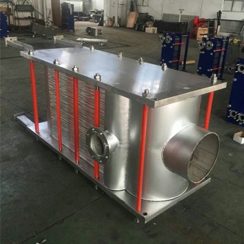 15. Quick Heat Exchanger Calculation Example
Consider a water-to-water application.
Hot Side
Flow:
10 kg/s
Inlet:
80°C
Outlet:
60°C
Cold Side
Inlet:
25°C
Outlet:
45°C
Assume:
Cp = 4.18 kJ/kg·K
Step 1 — Calculate Heat Duty
Q = 10 × 4.18 × 20
Q = 836 kW
Step 2 — Calculate LMTD
ΔT₁ = 80 − 45 = 35 K
ΔT₂ = 60 − 25 = 35 K
Therefore:
LMTD = 35 K
Step 3 — Assume Preliminary U
Assume:
U = 1,500 W/m²·K
Step 4 — Calculate Area
A = 836,000 ÷ (1,500 × 35)
A ≈ 15.9 m²
Preliminary Result
Heat duty ≈ 836 kW
LMTD = 35 K
Calculated thermal area ≈ 16 m²
Again, this is a preliminary calculation, not a final equipment selection.
16. Why Your Calculator Result May Differ From a Manufacturer’s Selection
You may calculate:
16 m²
while a manufacturer’s selection software recommends a different area.
That does not necessarily mean one calculation is wrong.
The manufacturer’s detailed calculation may include:
- Actual plate geometry
- Number of plates
- Channel arrangement
- Flow velocity
- Local heat-transfer coefficients
- Pressure drop
- Port losses
- Fouling allowance
- Material properties
- Temperature-dependent fluid properties
- Design margin
- Mechanical constraints
Professional heat exchanger selection tools are designed to combine thermal and hydraulic requirements rather than relying on area alone. Alfa Laval, for example, describes its PHE Select tool as a selection system for matching plate heat exchangers to specific applications.
17. Heat Exchanger Area Is Not the Same as Equipment Size
This distinction is important.
When an engineer says:
“I need 20 m² of heat-transfer area.”
that does not mean the physical exchanger will occupy exactly a particular volume.
For a plate heat exchanger, the total area depends on:
- Number of plates
- Effective plate area
- Plate dimensions
- Plate pattern
- Channel arrangement
For a shell-and-tube exchanger, area depends on:
- Tube outside diameter
- Tube length
- Number of tubes
- Tube arrangement
- Number of passes
Therefore:
Heat-transfer area ≠ external equipment dimensions
The required thermal area is only one part of the equipment design.
18. Heat Exchanger Calculation for Steam Heating
The calculation changes when one side involves phase change.
For example, when steam condenses, the steam-side temperature can remain approximately constant over the condensation section at a given pressure.
The heat duty may be estimated from:
Q = ṁsteam × hfg
Where:
- ṁsteam = steam mass flow rate
- hfg = latent heat of vaporization
The required heat-transfer area can then be estimated from:
A = Q ÷ (U × ΔT)
But real steam systems can involve:
- Superheated steam
- Desuperheating
- Condensation
- Condensate subcooling
- Non-condensable gases
In these cases, a single simple LMTD calculation may not adequately represent the entire duty. Engineering references distinguish these zones because both temperature difference and heat-transfer coefficient can change across the process.
19. Heat Exchanger Calculation for Glycol
Glycol systems require more care than water systems.
The concentration affects:
- Density
- Specific heat
- Viscosity
- Thermal conductivity
- Pressure drop
- Heat-transfer coefficient
For example:
30% glycol
and
50% glycol
cannot simply be treated as water with different freezing points.
A higher glycol concentration can increase viscosity and affect the hydraulic and thermal performance of the exchanger.
Therefore, provide the exact glycol concentration when requesting a heat exchanger selection.
20. Heat Exchanger Calculation for Oil
Oil applications require particular attention to viscosity.
A high-viscosity oil can have a substantially lower heat-transfer coefficient than water.
The result can be:
Lower U value
→
More required heat-transfer area
→
Different flow-channel requirements
→
Different pressure-drop considerations
For oil cooling or heating, provide:
- Oil type
- Operating temperature
- Flow rate
- Viscosity at operating temperature
- Specific heat
- Density
If viscosity data is available at multiple temperatures, provide it.
21. What Information Should You Send for a Final Heat Exchanger Selection?
For a preliminary calculation:
Fluid
Flow rate
Four temperatures
Heat duty
Maximum pressure drop
may be sufficient to start.
For a final selection, also provide:
- Operating pressure
- Design pressure
- Operating temperature
- Design temperature
- Fluid concentration
- Viscosity
- Fouling conditions
- Material requirements
- Connection size
- Installation restrictions
- Applicable standards
This is why an online calculator should be treated as a preliminary sizing tool, not a replacement for detailed thermal and mechanical engineering.
22. Heat Exchanger Sizing Checklist
Before calculating or requesting a quotation, check:
Thermal
☐ Heat duty
☐ Hot-side inlet temperature
☐ Hot-side outlet temperature
☐ Cold-side inlet temperature
☐ Cold-side outlet temperature
☐ Flow rate on both sides
Fluid
☐ Fluid type
☐ Density
☐ Specific heat
☐ Viscosity
☐ Thermal conductivity
☐ Concentration
Hydraulic
☐ Maximum allowable pressure drop
☐ Minimum flow
☐ Maximum flow
Mechanical
☐ Operating pressure
☐ Design pressure
☐ Operating temperature
☐ Design temperature
Design
☐ Fouling conditions
☐ Material requirements
☐ Connection requirements
☐ Installation limitations
A complete calculation starts with complete input data.
23. Heat Exchanger Sizing Calculator: The Basic Workflow
A practical calculation can be summarized as:
Step 1 — Define the process
Identify both fluids and operating conditions.
↓
Step 2 — Calculate heat duty
Q = ṁ × Cp × ΔT
↓
Step 3 — Calculate temperature driving force
Calculate LMTD for the selected flow arrangement.
↓
Step 4 — Estimate overall heat-transfer coefficient
Select a reasonable preliminary U value based on the application.
↓
Step 5 — Calculate theoretical area
A = Q ÷ (U × LMTD)
↓
Step 6 — Check fouling and design margin
Adjust the design according to the application.
↓
Step 7 — Check pressure drop
Confirm that both sides remain within the allowable pressure-drop limit.
↓
Step 8 — Select the actual heat exchanger
Check plate/tube geometry, number of plates/tubes, connections, materials and mechanical design.
This is the difference between a simple heat-transfer calculation and an actual heat exchanger selection.
24. When an Online Calculator Is Not Enough
A simple calculator is useful for:
- Preliminary sizing
- Budget estimates
- Comparing alternatives
- Checking an existing calculation
- Preparing an RFQ
- Understanding the approximate heat-transfer area
It should not be the sole basis for final equipment selection when the application involves:
- High pressure
- High temperature
- Refrigerants
- Steam
- Two-phase flow
- Highly viscous fluids
- Corrosive chemicals
- Seawater
- Significant fouling
- Strict pressure-drop limits
- Critical process applications
These applications require a detailed thermal and mechanical assessment.
25. Do Not Select a Heat Exchanger From Area Alone
Two heat exchangers can have the same nominal heat-transfer area and produce different results.
Performance depends on:
Area + U + LMTD + flow arrangement + pressure drop + fouling + fluid properties
Therefore, when comparing supplier quotations, do not compare only:
“20 m² vs. 25 m².”
Also compare:
- Heat duty
- Inlet/outlet temperatures
- Flow rates
- Pressure drop
- Materials
- Design pressure
- Design temperature
- Fouling assumptions
- Number of plates/tubes
- Connection size
- Operating conditions
A larger quoted area does not automatically mean a better heat exchanger.
Heat Exchanger Sizing Calculator: Final Formula Sheet
For quick reference:
Heat Duty
Q = ṁ × Cp × ΔT
Heat Transfer
Q = U × A × LMTD
Required Area
A = Q ÷ (U × LMTD)
Log Mean Temperature Difference
LMTD = (ΔT₁ − ΔT₂) ÷ ln(ΔT₁ / ΔT₂)
For counter-current flow:
ΔT₁ = T_hot,in − T_cold,out
ΔT₂ = T_hot,out − T_cold,in
Volumetric Flow to Mass Flow
ṁ = ρ × V
These formulas provide the foundation for preliminary heat exchanger sizing.
But the final equipment selection must also satisfy hydraulic, mechanical, material and fouling requirements.
Need a Heat Exchanger Calculation or Quote?
If you already know your process conditions, send:
Hot-side fluid
Cold-side fluid
Hot-side flow rate
Cold-side flow rate
Hot-side inlet/outlet temperatures
Cold-side inlet/outlet temperatures
Heat duty, if known
Maximum allowable pressure drop
Operating pressure
Fluid concentration, if applicable
With this information, a preliminary heat exchanger calculation can determine the approximate heat duty, LMTD and required heat-transfer area, followed by a detailed thermal and hydraulic selection.
Use the calculator for the first estimate. Use the actual process data for the final heat exchanger selection.