For most clean, low-to-medium pressure applications with moderate temperatures, a plate heat exchanger (PHE) is the better choice because it delivers a closer temperature approach, higher thermal efficiency, and a smaller footprint at a lower installed cost. Choose a shell and tube heat exchanger (STHE) when you face high pressure, high temperature, heavy fouling, large capacity, or aggressive fluids that gaskets cannot handle.
This article explains exactly how to decide between the two, using real selection logic, formulas, and parameters. You will learn:
The working principles and construction of each type
How to compare pressure drop, temperature approach, and fouling
Material and gasket selection rules
A step-by-step selection guide and a pre-purchase checklist
Common mistakes, cost drivers, lead times, and certification factors
Answers to the questions engineers and buyers ask most
Quick Answer
| Question | Short Answer |
|---|---|
| Which is more efficient? | Plate heat exchanger, typically 3–5× higher heat transfer coefficient per unit area |
| Which handles high pressure? | Shell and tube, commonly up to 100+ bar; gasketed PHE usually ≤ 25 bar |
| Which resists fouling better? | Shell and tube, especially with removable tube bundles |
| Which costs less for the same duty? | Plate heat exchanger, often 30–60% lower installed cost for clean duty |
| Which is easier to expand? | Plate heat exchanger, add plates within frame capacity |
Table of Contents
What Is a Plate Heat Exchanger?
What Is a Shell and Tube Heat Exchanger?
Plate vs Shell and Tube: Direct Comparison Table
How to Compare Thermal Performance and Temperature Approach
Pressure Drop: Why It Decides Many Projects
Fouling, Maintenance, and Cleaning
Material and Gasket Selection
Step-by-Step Selection Guide
Cost, Lead Time, and Certification Factors
Common Mistakes and How to Avoid Them
Pre-Purchase Checklist
FAQ
Key Takeaways
What Is a Plate Heat Exchanger?
A plate heat exchanger is a compact unit built from a stack of corrugated metal plates clamped between two frames. Hot and cold fluids flow through alternate channels, transferring heat across the thin plate wall.
Key characteristics:
Types: gasketed, brazed, welded, semi-welded, and plate-and-frame
Plate materials: 316L stainless steel, titanium, SMO 254, nickel alloys
Gasket materials: NBR, EPDM, HNBR, FKM (Viton-compatible), PTFE-encapsulated
Typical pressure: up to 25 bar for gasketed; brazed units can reach 30–45 bar
Typical temperature: −35 °C to 200 °C depending on gasket
Heat transfer coefficient: 3,000–7,000 W/m²·K (water-to-water)
The corrugated plate pattern creates turbulent flow at low Reynolds numbers, which is why a plate heat exchanger achieves high efficiency in a small volume.
H3: When a Plate Heat Exchanger Is the Right Choice
Clean or slightly fouling fluids
Close temperature approach required (as low as 1 °C)
Limited floor space or weight budget
HVAC, district heating, food and beverage, data center cooling, heat pumps
Moderate pressure and temperature
Need for future capacity expansion by adding plates
What Is a Shell and Tube Heat Exchanger?
A shell and tube heat exchanger consists of a cylindrical shell containing a bundle of tubes. One fluid flows through the tubes (tube side); the other flows across the tubes inside the shell (shell side).
Key characteristics:
Types: fixed tube sheet, U-tube, floating head, kettle, double pipe
Tube materials: carbon steel, stainless steel, copper alloys, titanium, duplex
Typical pressure: up to 100+ bar, with high-pressure designs beyond that
Typical temperature: −100 °C to 600 °C with correct materials
Heat transfer coefficient: 500–1,500 W/m²·K (water-to-water)
Standards: TEMA, ASME Section VIII, PED, API 660
Shell and tube units are robust, tolerant of fouling, and well suited to high-energy duties in chemical, power, oil and gas, and marine applications.
H3: When a Shell and Tube Heat Exchanger Is the Right Choice
High pressure or high temperature
Heavy fouling, scaling, or particulate-laden fluids
Large heat duty (multi-MW)
Toxic, flammable, or volatile fluids requiring robust sealing
Steam condensation or boiling duties
Thermal cycling and mechanical stress
Applications where tube cleaning or replacement is routine
Plate vs Shell and Tube: Direct Comparison Table
| Parameter | Plate Heat Exchanger | Shell and Tube Heat Exchanger |
|---|---|---|
| Heat transfer efficiency | High (3–5× per unit area) | Moderate |
| Temperature approach | 1–3 °C | 5–10 °C typical |
| Footprint | 10–30% of STHE | Large |
| Weight | Low | High |
| Max pressure | ~25 bar (gasketed) | 100+ bar |
| Max temperature | ~200 °C (gasket limit) | 600 °C+ |
| Fouling resistance | Lower tolerance | Higher tolerance |
| Cleaning | CIP or manual plate opening | Tube cleaning, bundle removal |
| Expansion capacity | Add plates (within frame) | Fixed, or replace unit |
| Leak path | External (gasket) | Internal or tube sheet |
| Installed cost (clean duty) | Lower | Higher |
| Maintenance skill | Moderate | Moderate to high |
| Best for | Clean fluids, tight approach | High P/T, fouling, large duty |
How to Compare Thermal Performance and Temperature Approach
Thermal performance comparison starts with the basic heat transfer equation:
Q = U × A × LMTD
Where:
Q = heat duty (W)
U = overall heat transfer coefficient (W/m²·K)
A = heat transfer area (m²)
LMTD = log mean temperature difference (K)
Because a plate heat exchanger achieves a much higher U, it needs far less area A for the same duty Q. This is why plate units are compact.
H3: Why Temperature Approach Matters
Temperature approach is the smallest temperature difference between the hot and cold fluids at either end of the exchanger.
PHE: approach down to 1 °C is achievable
STHE: approach below 5 °C becomes expensive because area grows rapidly
A close approach is critical in:
Heat recovery systems
District heating and cooling
Heat pumps
Chiller and condenser circuits
Data center liquid cooling
If your process requires a 2 °C approach, a plate heat exchanger is usually the only economical option.
H3: Overall Heat Transfer Coefficient (U) Comparison
| Duty | PHE U (W/m²·K) | STHE U (W/m²·K) |
|---|---|---|
| Water–water | 3,000–7,000 | 500–1,500 |
| Steam–water | 3,000–6,000 | 800–1,500 |
| Oil–water | 300–1,000 | 100–400 |
| Gas–liquid | 50–300 | 20–100 |
Higher U means smaller area, lower weight, and often lower cost — as long as fouling and pressure allow.
Pressure Drop: Why It Decides Many Projects
Pressure drop determines pump power, operating cost, and whether a design is even feasible. Both exchanger types must meet the allowable pressure drop on each side.
H3: Typical Allowable Pressure Drop
| Side | Typical Allowable ΔP |
|---|---|
| Pumped liquid | 50–100 kPa |
| Cooling water | 30–80 kPa |
| Steam | 10–30 kPa |
| Gas | 1–5 kPa |
| Viscous fluid | 100–150 kPa |
H3: How Each Type Behaves
PHE: Narrow channels and corrugations create high turbulence → high U but also higher ΔP per pass. Plate geometry (chevron angle) can be tuned to trade U against ΔP.
STHE: Larger flow area → lower ΔP, but lower U. Baffle spacing and tube count can be adjusted.
Rule of thumb: If allowable ΔP is tight and the fluid is clean, a PHE with a wide-angle plate may work. If ΔP is tight and the fluid is dirty or viscous, STHE is safer.
Fouling, Maintenance, and Cleaning
Fouling is the single biggest reason projects switch from PHE to STHE. It reduces U, raises ΔP, and increases downtime.
H3: Fouling Factors by Application
| Fluid | Typical Fouling Factor (m²·K/W) |
|---|---|
| Clean water | 0.0001 |
| Cooling tower water | 0.0002–0.0004 |
| River water | 0.0004–0.0008 |
| Oil | 0.0003–0.0006 |
| Steam | 0.0001 |
| Process fluid with solids | 0.0005–0.001 |
H3: Cleaning Comparison
| Method | PHE | STHE |
|---|---|---|
| CIP (clean-in-place) | Yes, common | Limited |
| Manual plate opening | Yes | No |
| Tube brushing / hydrojetting | No | Yes |
| Bundle removal | No | Yes |
| Downtime | Short | Longer |
| Skill required | Moderate | Higher |
H3: Which Fouls Less?
The myth is that PHEs foul more. In reality, the high turbulence in a PHE reduces fouling for many fluids — but narrow channels block faster when solids are present. STHE handles solids better because tube diameters are larger and bundles can be removed.
Practical rule: If your fluid has fibers, particles, or crystallizing salts, favor shell and tube or a welded/wide-gap plate design.
 Material and Gasket Selection
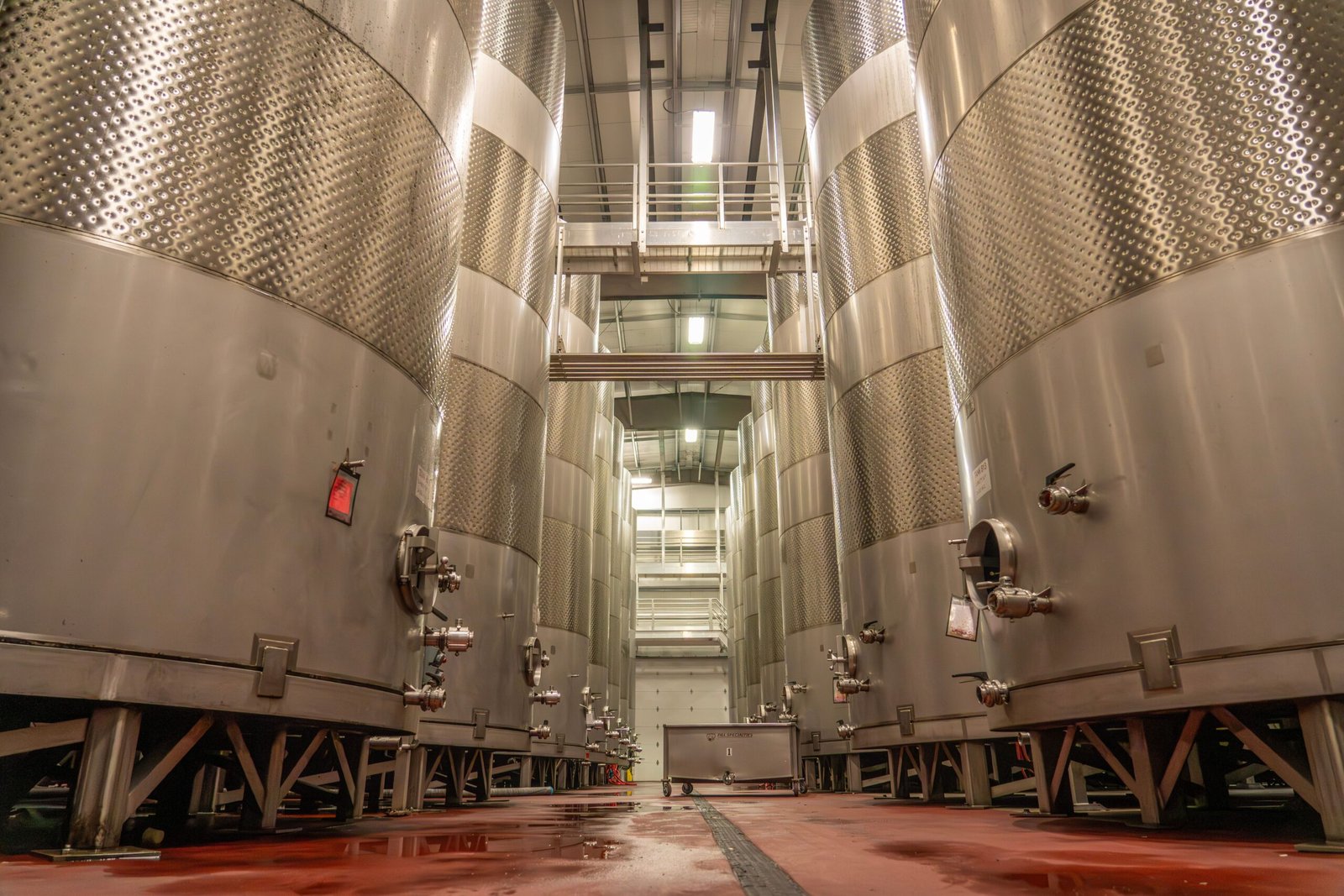 Material and Gasket Selection
Material choice affects corrosion resistance, cost, and lead time.
H3: Plate and Tube Material Selection
| Fluid | Recommended Material |
|---|---|
| Clean water, HVAC | 316L stainless steel |
| Seawater, chloride-rich | Titanium, SMO 254, duplex |
| Ammonia | Carbon steel (STHE), 316L (PHE) |
| Food and beverage | 316L, FDA-compliant gaskets |
| Acids / aggressive chemicals | Nickel alloys, titanium, PTFE-lined |
| High-temperature steam | Carbon steel, chrome-moly |
H3: Gasket Selection (PHE)
| Gasket | Temp Range | Best For |
|---|---|---|
| NBR | −20 to 110 °C | Water, oils, general HVAC |
| EPDM | −35 to 150 °C | Hot water, steam, glycol |
| HNBR | −20 to 160 °C | Oils, refrigerants |
| FKM (Viton-compatible) | −20 to 200 °C | Aggressive chemicals, high temp |
| PTFE-encapsulated | −20 to 180 °C | Highly corrosive fluids |
H3: Shell and Tube Material Notes
Tube sheet and shell materials must match thermal expansion behavior
U-tube and floating head designs handle thermal expansion better than fixed tube sheet
Consider corrosion allowance for carbon steel in wet or marine environments
Step-by-Step Selection Guide
Follow these steps to choose between a plate and shell and tube heat exchanger.
Step 1 — Define the duty.
Calculate Q from mass flow, specific heat, and temperature change:
Q = ṁ × cp × ΔT
Step 2 — List fluid properties.
Density, viscosity, specific heat, thermal conductivity, fouling tendency, and corrosivity.
Step 3 — Establish design conditions.
Pressure, temperature, allowable pressure drop on each side, and design codes (PED, ASME, TEMA).
Step 4 — Check temperature approach.
If approach < 3 °C, a PHE is usually required.
Step 5 — Check pressure and temperature limits.
If > 25 bar or > 200 °C, default to shell and tube unless a welded PHE is justified.
Step 6 — Evaluate fouling.
High solids, fibers, or scaling → STHE or wide-gap PHE.
Step 7 — Calculate required area.
A = Q / (U × LMTD). Compare area for both types.
Step 8 — Compare pressure drop.
Ensure ΔP is within pump or system limits.
Step 9 — Check footprint, weight, and installation.
PHE saves space; STHE may need foundations and rigging.
Step 10 — Compare total cost.
Include equipment, installation, maintenance, and energy over life.
Step 11 — Confirm materials and certifications.
Match wetted materials to fluids and market requirements.
Step 12 — Verify supplier capability.
Ask for thermal calculations, drawings, and test certificates.
Cost, Lead Time, and Certification Factors
H3: Cost Drivers
| Factor | PHE Impact | STHE Impact |
|---|---|---|
| Plate/tube material | High | High |
| Gasket material | Moderate | N/A |
| Frame size | Moderate | N/A |
| Shell thickness | N/A | High |
| Pressure rating | High (welded) | Moderate |
| Custom design | Moderate | High |
| Installation | Low | High |
| Maintenance | Low–moderate | Moderate–high |
General guidance: For clean, moderate-duty applications, a plate heat exchanger often costs 30–60% less installed. For high-pressure or heavy fouling, shell and tube is more economical over life.
H3: Lead Time Factors
Standard PHE: 2–4 weeks
Custom PHE: 4–8 weeks
Standard STHE: 6–10 weeks
Custom STHE with exotic materials: 10–16 weeks
Certification (PED, ASME U-stamp): adds 2–6 weeks
Lead time is affected by material availability, plate/tube tooling, and third-party inspection.
H3: Certification Factors
| Market | Common Requirements |
|---|---|
| Europe | PED 2014/68/EU, CE marking, EN 13445 |
| North America | ASME Section VIII, U-stamp, CRN (Canada) |
| Middle East | ASME, PED, or local authority approval |
| Southeast Asia | ASME, PED, or national standards |
| Marine | ABS, DNV, Lloyd’s Register |
| Food / pharma | FDA-compliant materials, 3-A, EHEDG |
Always confirm certification requirements before ordering. Retrofitting certification after manufacturing is expensive.
Common Mistakes and How to Avoid Them
1. Choosing PHE for a fouling fluid.
Avoid by reviewing solids content and cleaning access first. Use STHE or wide-gap PHE.
2. Ignoring allowable pressure drop.
A design that meets duty but exceeds ΔP will fail in operation. Always specify ΔP limits.
3. Undersizing for future capacity.
Select a PHE frame that allows adding plates, or size STHE with margin.
4. Using the wrong gasket material.
A gasket incompatible with the fluid will fail early. Match gasket to fluid and temperature.
5. Skipping fouling factors.
Ignoring fouling leads to oversized or undersized units and unexpected downtime.
6. Mixing materials incorrectly.
Dissimilar metals can cause galvanic corrosion. Check material compatibility.
7. Assuming all PHEs are gasketed.
Brazed and welded PHEs handle higher pressure and temperature but are not serviceable.
8. Forgetting certification requirements.
PED, ASME, or marine approvals must be planned from the start.
9. Overlooking installation and maintenance access.
STHE needs space for bundle removal; PHE needs space for plate opening.
10. Buying on price alone.
Cheapest unit may have higher operating cost, shorter life, or no spare parts support.
Pre-Purchase Checklist
Use this checklist before confirming any heat exchanger order.
- □
Heat duty (Q) calculated and verified
- □
Fluid properties confirmed (density, viscosity, cp, k)
- □
Design pressure and temperature defined
- □
Allowable pressure drop specified per side
- □
Temperature approach confirmed feasible
- □
Fouling factors selected
- □
Material compatibility checked
- □
Gasket material matched (PHE)
- □
Certification requirements identified
- □
Footprint, weight, and access verified
- □
Maintenance and cleaning method planned
- □
Spare parts strategy defined (plates, gaskets, tubes)
- □
Supplier thermal calculation and drawing requested
- □
Test certificates and traceability confirmed
- □
Lead time and delivery terms agreed
FAQ
1. Which is better, a plate or shell and tube heat exchanger?
Neither is universally better. Plate heat exchangers win for clean fluids, close temperature approach, low pressure, and compact space. Shell and tube win for high pressure, high temperature, heavy fouling, and large duties.
2. What is the maximum pressure for a plate heat exchanger?
Gasketed plate heat exchangers typically handle up to 25 bar. Brazed and welded designs can reach 30–45 bar, depending on size and construction.
3. Can a plate heat exchanger replace a shell and tube unit?
Yes, in many clean-fluid applications. A plate heat exchanger can be a compatible replacement when pressure, temperature, and fouling conditions allow. Always verify ΔP and material compatibility.
4. How do I calculate the required heat transfer area?
Use A = Q / (U × LMTD). Q is the duty, U is the overall heat transfer coefficient, and LMTD is the log mean temperature difference. Confirm U from vendor data or reference tables.
5. Which type has lower pressure drop?
Shell and tube usually has lower pressure drop because of larger flow areas. Plate heat exchangers have higher ΔP per pass but can be configured with multiple passes or wider plate channels.
6. How often do plate heat exchanger gaskets need replacement?
Typically every 5–10 years, depending on temperature, fluid, and operating cycles. Harsh chemicals or frequent thermal cycling shorten gasket life.
7. Which is easier to clean?
Plate heat exchangers are easier for CIP and manual plate cleaning. Shell and tube units require tube brushing, hydrojetting, or bundle removal, which is more labor-intensive.
8. What is the typical temperature approach for each type?
Plate heat exchangers can achieve 1–3 °C approach. Shell and tube typically need 5–10 °C for economical design.
9. Can I use a plate heat exchanger for steam?
Yes, with the correct gasket and plate material. EPDM or FKM gaskets and 316L plates are common for steam duties within temperature limits.
10. What certifications should I look for?
For Europe, PED and CE marking. For North America, ASME Section VIII and U-stamp. For marine, ABS, DNV, or Lloyd’s Register. Food and pharma may need FDA, 3-A, or EHEDG compliance.
11. How much does a plate heat exchanger cost compared to shell and tube?
For clean, moderate-duty applications, a plate heat exchanger often costs 30–60% less installed. For high-pressure or fouling duties, shell and tube may be more economical over the full life cycle.
12. Can I add capacity to an existing heat exchanger?
Plate heat exchangers can often be expanded by adding plates if the frame has spare capacity. Shell and tube units generally cannot be expanded and may require a new unit.
Key Takeaways
Plate heat exchangers offer higher efficiency, closer temperature approach, and smaller footprint for clean, moderate-duty applications.
Shell and tube heat exchangers are the better choice for high pressure, high temperature, heavy fouling, and large capacities.
Pressure drop, fouling, and temperature approach are the three factors that most often decide the selection.
Material and gasket selection must match the fluid, temperature, and certification requirements.
Total cost of ownership — not purchase price — should guide the final decision.
Certification (PED, ASME, marine) must be planned before ordering to avoid delays.
A pre-purchase checklist reduces the risk of undersizing, premature failure, and downtime.
Work with a supplier who provides thermal calculations, drawings, and after-sales support, not just a price.