Air heat recovery captures useful thermal energy from exhaust or return air and transfers it to incoming fresh air, reducing the heating or cooling load of an HVAC or industrial ventilation system. The most common solutions use air-to-air heat exchangers, including plate heat exchangers, rotary heat exchangers, heat pipes, and run-around coil systems.
The right design is not simply the exchanger with the highest rated heat-recovery efficiency. Engineers must balance airflow, supply and exhaust temperatures, temperature efficiency, pressure drop, fan energy, cross-contamination risk, condensation, frost, fouling, materials, maintenance, and total cost.
This guide explains how air heat recovery works, how to calculate recoverable heat, how to compare heat exchanger technologies, and how to select and size an air heat recovery system for commercial and industrial applications.
Table of Contents
- Quick Answer: What Is Air Heat Recovery?
- How Does Air Heat Recovery Work?
- What Types of Air Heat Recovery Heat Exchangers Are Available?
- How Much Energy Can Air Heat Recovery Save?
- How Do Temperature Efficiency, Pressure Drop, and Airflow Affect Selection?
- How to Size and Select an Air Heat Recovery Heat Exchanger
- How Do Condensation, Frost, Fouling, Materials, and Maintenance Affect Air Heat Recovery?
- How Much Does an Air Heat Recovery System Cost?
- Common Mistakes in Air Heat Recovery Projects
- Air Heat Recovery Selection Checklist
- FAQ
- Key Takeaways
Quick Answer: What Is Air Heat Recovery?
Air heat recovery is the process of transferring heat between exhaust/return air and incoming fresh air without normally mixing the two air streams.
For heating applications:
Warm exhaust air → heat exchanger → cold outdoor air becomes warmer
For cooling applications:
Cool return/exhaust air → heat exchanger → hot outdoor air becomes cooler
The recovered sensible heat can reduce the capacity required from:
- Boilers
- Electric heaters
- Heat pumps
- Chillers
- DX systems
- Cooling coils
Depending on the heat exchanger technology, the system may also recover part of the latent heat associated with moisture.
Quick Comparison
| Technology | Heat Transfer | Moisture Transfer | Cross-Contamination Risk | Typical Application |
|---|---|---|---|---|
| Plate heat exchanger | Sensible, some designs latent | Low to possible | Low | HVAC ventilation |
| Rotary heat exchanger | Sensible + latent | Yes, depending on rotor | Some transfer potential | Large air-handling systems |
| Heat pipe | Sensible | No | Very low | HVAC, process air |
| Run-around coil | Sensible | No | Very low | Separate air streams |
| Air-to-air coil system | Sensible | No | Very low | Industrial HVAC |
How Does Air Heat Recovery Work?
An air heat recovery system uses a heat-transfer device to recover thermal energy from one air stream and transfer it to another air stream while controlling airflow, temperature, and pressure losses.
Basic Air Heat Recovery Process
Consider a winter ventilation system.
Outdoor air enters at 0°C.
Exhaust air leaves the building at 22°C.
Instead of exhausting the warm air directly outdoors, the heat exchanger transfers part of its heat to the incoming outdoor air.
For example:
- Outdoor air: 0°C
- Exhaust air: 22°C
- Supply air after recovery: 16°C
The heating system then needs to raise the air temperature from approximately 16°C to the final supply temperature rather than from 0°C.
This can substantially reduce heating demand when airflow and operating hours are high.
Sensible Heat Recovery
Sensible heat recovery transfers temperature-related energy.
The approximate sensible heat transfer is:
Q = ṁ × Cp × ΔT
For air:
- Q = heat transfer
- ṁ = air mass flow rate
- Cp = specific heat of air
- ΔT = temperature change
For HVAC calculations, the air volume flow rate is often used together with air density.
Latent Heat Recovery
Latent heat recovery transfers moisture-related energy as well as sensible heat.
This can occur with:
- Enthalpy wheels
- Desiccant-based rotary systems
- Membrane-type heat exchangers
- Other moisture-permeable technologies
Latent heat recovery can be particularly useful when humidity control represents a significant portion of the HVAC load.
What Types of Air Heat Recovery Heat Exchangers Are Available?
The most suitable air heat recovery technology depends on airflow arrangement, required efficiency, pressure drop, humidity, contamination risk, maintenance requirements, and available installation space.
Plate Air-to-Air Heat Exchanger
A plate air-to-air heat exchanger separates the two air streams using thin heat-transfer plates.
Common flow arrangements include:
- Cross-flow
- Counter-flow
- Cross-counter-flow
Advantages include:
- No rotating components
- No direct mixing under normal operation
- Compact construction
- Relatively simple maintenance
- No electrical drive required
Potential limitations include:
- Pressure drop
- Frost risk
- Condensation management
- Limited moisture transfer for sensible-only designs
Gasketed Plate Heat Exchanger
Gasketed plate technology is widely used for liquid-to-liquid applications but can also be considered for specialized air or gas duties depending on the design.
For general ventilation air heat recovery, dedicated air-to-air plate constructions are usually more appropriate.
Rotary Heat Exchanger
A rotary heat exchanger uses a rotating heat-storage matrix to transfer heat between exhaust and supply air streams.
It can recover:
- Sensible heat
- Latent heat, depending on rotor construction
Advantages:
- High heat recovery potential
- Suitable for large air-handling systems
- Can recover moisture
- Compact for high airflow applications
Potential concerns:
- Rotating components
- Drive motor maintenance
- Seal leakage
- Some degree of air carryover or cross-contamination
- Control requirements
Heat Pipe Heat Exchanger
A heat pipe exchanger uses sealed heat pipes to transfer heat between air streams.
Advantages include:
- No mechanical drive
- No direct fluid pumping between streams
- Low cross-contamination risk
- Relatively simple operation
It transfers sensible heat rather than moisture under normal operation.
Run-Around Coil System
A run-around system uses two coils connected by an intermediate fluid circuit.
The arrangement is:
Exhaust air → coil → circulating fluid → coil → fresh air
It is useful when the supply and exhaust air streams are physically separated.
Advantages:
- Very low direct cross-contamination risk
- Flexible equipment placement
- Suitable for remote or separated air streams
Disadvantages:
- Additional pump energy
- Two heat-transfer surfaces
- Additional piping
- More components
Technology Comparison
| Parameter | Plate | Rotary | Heat Pipe | Run-Around Coil |
|---|---|---|---|---|
| Sensible heat recovery | High potential | High potential | High potential | High potential |
| Latent recovery | Usually no | Possible | No | No |
| Moving parts | No | Yes | No | Pump |
| Cross-contamination potential | Low | Higher | Very low | Very low |
| Pump required | No | No | No | Yes |
| Frost risk | Yes | Yes | Yes | Lower depending on design |
| Maintenance complexity | Low–medium | Medium | Low | Medium |
| Separate air locations | Limited | Limited | Limited | Excellent |
| Typical scale | Small–large | Medium–large | Small–medium | Medium–large |
How Much Energy Can Air Heat Recovery Save?
Energy savings depend primarily on airflow, temperature difference, recovery efficiency, operating hours, outdoor conditions, and the efficiency of the heating or cooling system being displaced.
Basic Sensible Heat Calculation
The fundamental equation is:
Q = ṁ × Cp × ΔT
For air, a practical HVAC approximation can be written as:
Q(kW) ≈ 0.000335 × V̇(m³/h) × ΔT(°C)
This assumes typical air density and specific heat and is suitable for preliminary calculations.
Example
Suppose:
- Outdoor airflow = 10,000 m³/h
- Exhaust air temperature = 22°C
- Outdoor air temperature = 2°C
- Temperature recovery efficiency = 70%
The theoretical temperature difference is:
22 − 2 = 20°C
Approximate recovered temperature rise:
20 × 70% = 14°C
The supply air after recovery could therefore be approximately:
2 + 14 = 16°C
The approximate recovered sensible heat is:
Q ≈ 0.000335 × 10,000 × 14
Q ≈ 46.9 kW
This is a simplified estimate. Detailed design should use actual air density, humidity, pressure, altitude, heat exchanger performance data, and operating conditions.
Annual Energy Savings
If the heat recovery system provides an average useful recovery of 40 kW for 4,000 hours:
Annual recovered heat = 40 × 4,000
= 160,000 kWh/year
The actual energy purchased from the utility system will be lower or higher depending on the efficiency of the boiler, heat pump, electric heater, or other heat source being displaced.
How Do Temperature Efficiency, Pressure Drop, and Airflow Affect Selection?
A good air heat recovery design balances heat recovery efficiency against pressure drop because higher recovery performance can increase airflow resistance and fan energy.
Temperature Efficiency
A simplified sensible temperature efficiency can be expressed as:
ηt = (T_supply,out − T_supply,in) / (T_exhaust,in − T_supply,in)
Where:
- T_supply,in = incoming outdoor-air temperature
- T_supply,out = supply-air temperature after recovery
- T_exhaust,in = exhaust-air temperature entering the exchanger
For example:
- Outdoor air = 0°C
- Exhaust air = 20°C
- Supply air after recovery = 14°C
Then:
ηt = (14 − 0) / (20 − 0)
ηt = 70%
This is a simplified definition. Actual equipment ratings may use different test conditions and definitions.
Why Pressure Drop Matters
Air pressure drop increases fan power.
A simplified fan power relationship is:
P ≈ Qv × ΔP / η
Where:
- P = fan power
- Qv = volumetric airflow
- ΔP = pressure drop
- η = overall fan/motor efficiency
Therefore:
Higher heat recovery → potentially higher pressure drop → potentially higher fan energy
The system should be evaluated based on net energy savings, not exchanger efficiency alone.
Airflow Balance
Balanced supply and exhaust airflow generally improves predictable heat recovery.
Large differences between the two streams can affect:
- Heat-transfer effectiveness
- Pressure balance
- Building pressure
- Ventilation performance
- Cross-contamination risk
Heat Recovery vs Pressure Drop
| Design Approach | Heat Recovery | Pressure Drop | Fan Energy | Equipment Size |
|---|---|---|---|---|
| Low-resistance design | Moderate | Low | Low | Larger |
| Balanced design | High | Moderate | Moderate | Moderate |
| Maximum compactness | High | Higher | Higher | Smaller |
The optimum design depends on annual operating hours and energy prices.
How to Size and Select an Air Heat Recovery Heat Exchanger
Air heat recovery sizing should start with airflow and temperature conditions, then evaluate heat recovery, pressure drop, humidity, contamination, and physical installation requirements.
Step 1: Determine Airflow
Define:
- Supply airflow
- Exhaust airflow
- Minimum airflow
- Normal airflow
- Maximum airflow
- Operating schedule
Do not size only from maximum airflow if the system operates most of the year at partial load.
Step 2: Determine Temperature Conditions
Provide:
- Outdoor air temperature
- Exhaust/return air temperature
- Required supply temperature
- Heating design temperature
- Cooling design temperature
- Seasonal operating range
Step 3: Determine Humidity Conditions
For humid climates, determine:
- Outdoor relative humidity
- Exhaust relative humidity
- Dew point
- Condensation potential
- Required latent heat recovery
This is especially important in Southeast Asia, coastal regions, food plants, swimming pools, and other high-humidity environments.
Step 4: Define the Required Recovery
Determine whether the system needs:
- Sensible heat recovery only
- Sensible + latent heat recovery
- Heating recovery
- Cooling recovery
- Year-round operation
Step 5: Calculate Heat Recovery
Use:
Q = ṁ × Cp × ΔT
Then verify the manufacturer’s performance data at the actual operating point.
Step 6: Check Pressure Drop
Check pressure drop on both air sides.
Confirm that the existing fans can handle:
- Heat exchanger resistance
- Filters
- Ductwork
- Coils
- Dampers
- Other system components
Step 7: Select the Technology
Use application requirements to select:
- Plate exchanger
- Rotary exchanger
- Heat pipe
- Run-around coil
- Other custom air-to-air heat recovery solution
Step 8: Check Physical Installation
Confirm:
- Overall dimensions
- Duct connection size
- Service access
- Drainage
- Filter access
- Fan position
- Lifting requirements
- Insulation requirements
Step 9: Evaluate Economics
Calculate:
- Heat recovery
- Annual energy savings
- Fan energy penalty
- Equipment cost
- Installation cost
- Maintenance cost
- Payback period
Step 10: Confirm Compliance
Depending on the application and destination market, review applicable requirements for:
- HVAC equipment
- Fire safety
- Electrical components
- Pressure-containing components
- Materials
- Insulation
- Hygiene
- Marine applications
- Food-processing environments
Certification should be specified before manufacturing.
 How Do Condensation, Frost, Fouling, Materials, and Maintenance Affect Air Heat Recovery?
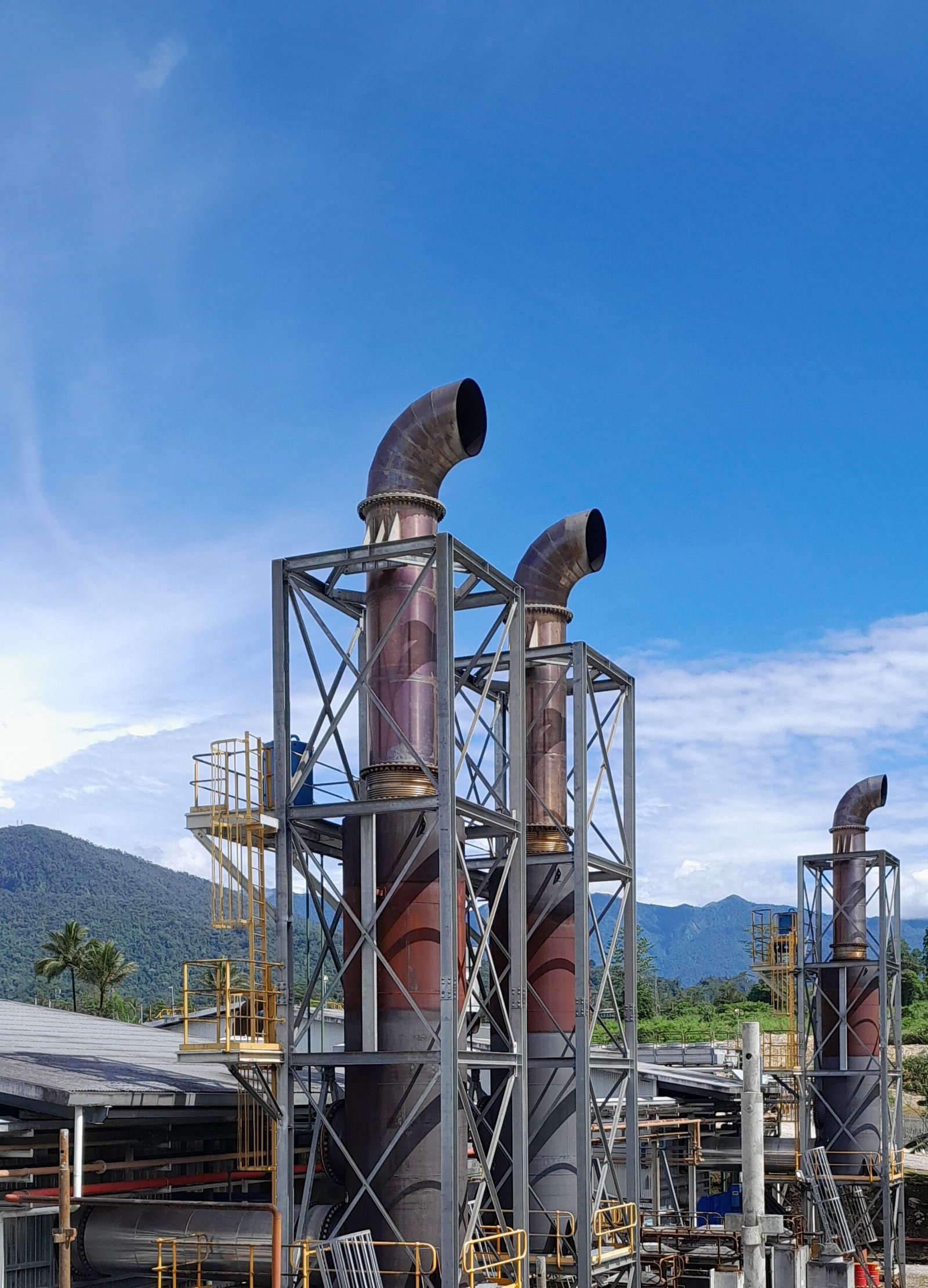 How Do Condensation, Frost, Fouling, Materials, and Maintenance Affect Air Heat Recovery?
Long-term air heat recovery performance depends heavily on moisture management, frost protection, air cleanliness, corrosion resistance, and access for inspection and cleaning.
Condensation
When warm humid exhaust air contacts a sufficiently cold heat-transfer surface, condensation can occur.
Condensation may be beneficial when latent heat recovery is intentionally designed.
However, uncontrolled condensation can cause:
- Water accumulation
- Corrosion
- Drainage problems
- Microbial growth
- Frost formation
A condensate drain may therefore be required.
Frost
In cold climates, moisture in exhaust air can freeze when the heat exchanger surface temperature falls below the freezing point.
Possible solutions include:
- Preheating
- Bypass control
- Variable airflow
- Defrost cycles
- Frost protection controls
- Special heat exchanger configurations
The correct strategy depends on climate and equipment design.
Fouling
Air-side fouling commonly comes from:
- Dust
- Fibers
- Oil mist
- Grease
- Industrial particles
- Biological contamination
A dirty heat exchanger causes:
- Higher pressure drop
- Lower heat recovery
- Higher fan energy
- Increased maintenance
Filters should therefore be considered part of the heat recovery system rather than an unrelated accessory.
Material Selection
Common heat exchanger materials may include:
- Aluminum
- Stainless steel
- Galvanized steel
- Coated metals
- Copper
- Specialized corrosion-resistant materials
Selection depends on:
- Air humidity
- Condensation
- Salt exposure
- Chemical contaminants
- Temperature
- Cleaning chemicals
For coastal or corrosive environments, material and coating selection become particularly important.
Maintenance
A practical maintenance program should include:
- Filter inspection
- Heat exchanger inspection
- Cleaning
- Condensate drain inspection
- Fan inspection
- Seal inspection
- Rotor/belt inspection where applicable
- Sensor verification
- Pressure-drop monitoring
- Frost-control inspection
A useful maintenance indicator is the change in pressure drop over time.
Increasing pressure drop can indicate fouling even before heat-recovery performance noticeably declines.
How Much Does an Air Heat Recovery System Cost?
Air heat recovery cost depends on airflow, exchanger technology, recovery efficiency, pressure drop, materials, controls, installation conditions, and certification requirements.
Main Cost Factors
| Cost Factor | Impact |
|---|---|
| Airflow capacity | Larger airflow usually requires larger equipment |
| Recovery efficiency | Higher performance can require more heat-transfer area |
| Pressure drop | Lower pressure drop may require larger equipment |
| Materials | Corrosion-resistant materials increase cost |
| Latent recovery | Moisture-transfer technology can increase complexity |
| Frost protection | Adds controls and components |
| Filters | Required filtration affects system cost and pressure drop |
| Controls | Sensors, actuators, and control panels add cost |
| Duct modifications | Can become a major installation cost |
| Maintenance access | May increase equipment footprint |
| Certification | Inspection and documentation may increase cost |
Simple Payback
A preliminary calculation is:
Payback Period = Total Investment / Annual Net Savings
Where:
Annual Net Savings = Heating/Cooling Energy Savings − Additional Fan Energy − Maintenance Costs
This calculation is more meaningful than comparing heat exchanger purchase prices alone.
Lead Time Considerations
Lead time can increase when a project requires:
- Non-standard airflow capacity
- Special materials
- High-temperature construction
- Corrosion-resistant coatings
- Integrated controls
- Custom dimensions
- Special electrical components
- Third-party inspection
- Custom OEM packaging
Standard equipment can usually be planned differently from a fully customized heat recovery package.
Common Mistakes in Air Heat Recovery Projects
The most common problems are incorrect airflow data, excessive pressure drop, poor condensation management, inadequate filtration, and evaluating efficiency without considering fan energy.
Mistake 1: Using Maximum Airflow as the Only Design Point
A system may operate most of the year below maximum airflow.
Solution: provide minimum, normal, and maximum airflow conditions.
Mistake 2: Looking Only at Heat Recovery Efficiency
A higher efficiency rating can come with higher pressure drop.
Solution: compare recovery efficiency and annual fan energy together.
Mistake 3: Ignoring Humidity
Sensible-only calculations may underestimate cooling loads in humid environments.
Solution: evaluate sensible and latent loads separately where humidity is important.
Mistake 4: Ignoring Condensation
Condensation can create drainage and corrosion problems.
Solution: check dew point, surface temperature, drainage, materials, and hygiene requirements.
Mistake 5: Ignoring Frost
Cold-climate operation can reduce airflow or damage equipment if frost protection is inadequate.
Solution: define the minimum outdoor temperature and design an appropriate defrost or bypass strategy.
Mistake 6: Underestimating Filter Pressure Drop
A heat exchanger may have acceptable pressure drop when clean but excessive system resistance after filter loading.
Solution: evaluate pressure drop across the complete air path.
Mistake 7: Poor Maintenance Access
A highly compact system can become difficult to clean.
Solution: provide adequate access for heat exchanger, filters, drains, seals, and moving components.
Mistake 8: Selecting Materials Without Considering Corrosion
Humid air, salt, and chemicals can accelerate corrosion.
Solution: evaluate air chemistry, condensation, and cleaning conditions before material selection.
Mistake 9: Ignoring Air Leakage and Cross-Contamination
Pressure differences and seal quality can affect air separation.
Solution: specify acceptable leakage levels and verify seals, casing construction, and pressure relationships.
Mistake 10: Calculating Savings From Peak Conditions
Peak recovery does not equal annual energy savings.
Solution: use actual hourly or seasonal operating profiles whenever possible.
Air Heat Recovery Selection Checklist
Use this checklist before ordering an air heat recovery heat exchanger or complete recovery system.
Airflow
Supply airflow confirmed
Exhaust airflow confirmed
Minimum airflow known
Normal airflow known
Maximum airflow known
Air density/altitude considered
Operating hours confirmed
Thermal Conditions
Outdoor air temperature defined
Exhaust air temperature defined
Supply air target defined
Heating condition checked
Cooling condition checked
Temperature recovery efficiency defined
Heat recovery duty calculated
Humidity
Outdoor humidity known
Exhaust humidity known
Dew point evaluated
Latent recovery requirement defined
Condensation risk evaluated
Frost risk evaluated
Hydraulic
Supply-side pressure drop checked
Exhaust-side pressure drop checked
Fan capacity checked
Fan power penalty calculated
Filter pressure drop included
Duct pressure losses included
Materials and Maintenance
Heat-transfer material selected
Corrosion risk evaluated
Coating requirements defined
Cleaning method defined
Filter access confirmed
Condensate drainage provided where required
Service access confirmed
Project and Compliance
Dimensions confirmed
Duct connections confirmed
Installation orientation confirmed
Control requirements defined
Electrical requirements confirmed
Certification requirements confirmed
Inspection requirements confirmed
Documentation requirements confirmed
Delivery schedule confirmed
FAQ
1. What is air heat recovery?
Air heat recovery is the process of transferring heat between exhaust or return air and incoming fresh air to reduce heating or cooling energy consumption.
2. How does an air-to-air heat exchanger save energy?
It transfers heat from one air stream to another. In winter, warm exhaust air preheats incoming outdoor air; in summer, cool return air can precool hot outdoor air.
3. What is the best heat exchanger for air heat recovery?
There is no universal best technology. Plate heat exchangers are suitable for many ventilation applications, rotary heat exchangers are attractive for large systems and latent recovery, while heat pipes and run-around coils can be useful where air streams must remain physically separated.
4. How do I calculate air heat recovery capacity?
Use Q = ṁ × Cp × ΔT. For preliminary HVAC calculations, Q(kW) ≈ 0.000335 × airflow(m³/h) × temperature change(°C) under typical air conditions.
5. What is a good air heat exchanger efficiency?
The required efficiency depends on climate, energy prices, airflow, pressure drop, equipment size, and project economics. A higher temperature efficiency is not automatically better if it creates excessive pressure drop and fan energy.
6. Does an air heat exchanger recover humidity?
A conventional sensible plate heat exchanger generally does not intentionally transfer moisture. Rotary enthalpy heat exchangers and certain membrane technologies can recover both sensible and latent energy.
7. What causes frost in an air heat recovery exchanger?
Frost forms when moist exhaust air reaches surfaces below the freezing point. It is most common in cold climates and requires appropriate frost protection, bypass, preheating, or defrost control.
8. How does pressure drop affect air heat recovery?
Pressure drop increases fan power consumption. A heat exchanger should therefore be selected by balancing heat recovery performance against pressure drop and annual fan energy.
9. Can air heat recovery work in humid climates?
Yes. However, humidity and condensation must be considered carefully. In humid climates, latent heat recovery may be valuable, while condensation management, corrosion resistance, drainage, and hygiene become more important.
10. How often should an air heat recovery heat exchanger be cleaned?
The required interval depends on air cleanliness, filtration, operating hours, humidity, and contamination. Pressure-drop trends and visual inspection are useful indicators for determining actual cleaning requirements.
11. What information is needed to select an air heat recovery heat exchanger?
Provide supply and exhaust airflow, inlet temperatures, humidity, operating conditions, required outlet temperature, allowable pressure drop, installation dimensions, contamination conditions, materials, controls, and operating schedule.
12. Can an air heat recovery system be customized for OEM applications?
Yes. OEM air heat recovery systems can be customized for airflow, heat recovery performance, dimensions, duct connections, materials, pressure drop, controls, electrical requirements, filtration, and installation conditions.
Key Takeaways
- Air heat recovery transfers useful thermal energy between exhaust and incoming air to reduce HVAC or industrial heating and cooling loads.
- The basic sensible heat calculation is Q = ṁ × Cp × ΔT.
- Plate, rotary, heat pipe, and run-around coil systems each have different advantages and limitations.
- Heat recovery efficiency must be evaluated together with pressure drop and fan energy.
- Humidity, condensation, and frost can significantly affect system performance and equipment selection.
- Fouling increases pressure drop and reduces heat-transfer performance, making filtration and maintenance important.
- Material selection should account for humidity, condensation, salt, chemicals, temperature, and cleaning conditions.
- The most accurate energy-saving estimate uses real airflow, temperature, humidity, operating-hour, and seasonal data, not only peak design conditions.