A data center cooling system removes the heat generated by servers, networking equipment, storage systems, and other electrical infrastructure. Its purpose is to maintain suitable operating conditions for IT equipment while controlling energy consumption and supporting reliable operation.
Unlike conventional building air conditioning, data center cooling must handle continuous heat loads, concentrated rack-level temperatures, changing IT workloads, and strict availability requirements.
A typical cooling system includes several interconnected components: precision air conditioning or liquid cooling equipment, pumps and fans, heat exchangers, chillers or dry coolers, and a control system that coordinates their operation.
The exact configuration depends on rack power density, facility size, climate, IT equipment specifications, and the required level of redundancy.
This guide explains how data center cooling systems work, how heat moves through the cooling infrastructure, what each major component does, and how operators can select and maintain an effective thermal management solution.
1. Why Do Data Centers Need Specialized Cooling Systems?
Servers generate heat whenever they consume electrical power. Processors, GPUs, memory modules, storage devices, power supplies, and networking components all contribute to the thermal load.
If this heat is not removed effectively, equipment temperatures can rise beyond acceptable operating limits.
Potential consequences include:
CPU and GPU thermal throttling
Reduced server performance
Unexpected equipment shutdowns
Accelerated component aging
Increased cooling-related energy consumption
Localized hot spots inside server racks
Reduced operational reliability
A data center cooling system must therefore do more than lower room temperature. It must deliver the required cooling capacity to the correct locations and maintain stable conditions as IT loads change.
1.1 How Servers Generate Heat
Almost all electrical power consumed by IT equipment ultimately becomes heat within the facility.
For an initial estimate:
Where:
\(Q_{\text{IT}}\) = heat generated by IT equipment
\(P_{\text{IT}}\) = electrical power consumed by IT equipment
Both values are expressed in kilowatts (kW).
For example, if a group of servers consumes 100 kW of electrical power, approximately 100 kW of heat must ultimately be removed from the IT environment.
This is a simplified estimate. A complete facility cooling load calculation must also consider UPS losses, power distribution losses, lighting, occupants, envelope heat gains, and other heat sources.
1.2 Why Temperature Distribution Matters
The average temperature of a server room does not necessarily indicate whether every server is receiving sufficient cooling.
Poor airflow distribution can cause some racks to overheat while other areas receive more cooling than necessary.
Common causes include:
Hot air recirculating into server intakes
Cold air bypassing server equipment
Blocked floor grilles or supply ducts
Poor rack arrangement
Missing blanking panels
Incorrect airflow balancing
Insufficient cooling near high-density racks
For this reason, modern data center thermal management focuses on server inlet conditions, airflow distribution, rack-level heat loads, and cooling system performance rather than room temperature alone.
2. How Does a Traditional Air-Cooled Data Center Cooling System Work?
Air cooling is widely used in enterprise data centers, colocation facilities, and conventional server environments.
The system works by circulating conditioned air through server racks, collecting heated exhaust air, and transferring the heat to a refrigeration or chilled-water system.
2.1 The Basic Air Cooling Process
A typical air-cooled data center follows this cycle:
Step 1: Cool air is supplied to the server room
CRAC units, CRAH units, or other precision air conditioning equipment deliver conditioned air to the IT environment.
The supply air may enter through a raised floor, overhead ductwork, or another engineered air distribution arrangement.
Step 2: Servers draw in cool air
Most conventional server racks use a front-to-back airflow arrangement.
Server fans draw cool air through the front of the equipment and move it across internal components.
Step 3: IT equipment transfers heat to the air
As air passes over processors, memory, power supplies, and other components, it absorbs heat.
The heated air exits through the rear of the server.
Step 4: Hot exhaust air returns to the cooling equipment
The heated air travels through a return-air pathway to the CRAC or CRAH unit.
Hot aisle and cold aisle arrangements help separate supply air from server exhaust air, reducing unwanted mixing.
Step 5: The cooling unit removes the heat
The cooling unit transfers heat from the return air into a refrigerant circuit or chilled-water loop.
The conditioned air is then supplied back to the server room.
This process repeats continuously while the IT equipment operates.
2.2 How Does a CRAC Unit Work?
A CRAC (Computer Room Air Conditioner) typically uses a direct-expansion refrigeration cycle to cool data center air.
Its main components commonly include:
Compressor
Evaporator coil
Condenser
Expansion device
Fans
Filters
Control system
The refrigeration process works as follows:
Warm return air passes across the evaporator coil.
Refrigerant absorbs heat from the air.
The compressor raises the refrigerant pressure and temperature.
The refrigerant releases heat through the condenser.
The expansion device reduces refrigerant pressure.
The refrigerant returns to the evaporator to absorb more heat.
Depending on the CRAC design, the condenser may be air-cooled or connected to another heat rejection arrangement.
CRAC units are often used where a dedicated direct-expansion cooling system is preferred.
2.3 How Does a CRAH Unit Work?
A CRAH (Computer Room Air Handler) uses a chilled-water coil rather than relying on an integral direct-expansion refrigeration cycle to cool the air.
The process is:
Warm return air passes through the CRAH unit.
Air flows across a chilled-water coil.
Heat transfers from the air into the water.
Cooled air is supplied back to the server room.
The warmed water returns to the central cooling plant for heat removal.
A CRAH system generally depends on a separate chilled-water plant, which may include chillers, pumps, heat exchangers, and heat rejection equipment.
Feature | CRAC | CRAH |
|---|---|---|
Main cooling method | Typically direct-expansion refrigeration | Chilled-water coil |
Heat transfer medium inside cooling coil | Refrigerant | Chilled water |
Refrigeration equipment | Commonly includes a compressor-based refrigeration circuit | Typically relies on a separate central chiller plant |
System configuration | Often dedicated or modular | Commonly integrated with central chilled-water infrastructure |
Key maintenance areas | Refrigerant circuit, compressor, coils, fans and filters | Water circuit, valves, coils, fans and filters |
The correct choice depends on facility design, available infrastructure, cooling capacity, redundancy, and lifecycle costs.
2.4 How Does Cold Aisle Containment Improve Cooling?
Cold aisle containment separates the cold air supplied to server fronts from the hot exhaust air leaving server rears.
Without effective separation, hot exhaust air may mix with cold supply air, reducing cooling effectiveness.
Cold aisle containment typically includes:
Physical aisle barriers
End-of-row doors
Roof or ceiling panels
Appropriate rack sealing
Blanking panels in unused rack spaces
By limiting air mixing, containment helps deliver more predictable server inlet conditions and can improve the effectiveness of existing cooling equipment.
It does not generate cooling capacity itself. The cooling units, air distribution system, and containment arrangement must be designed to work together.
3. How Does a Data Center Liquid Cooling System Work?
Liquid cooling removes heat using a circulating liquid rather than relying entirely on room-level airflow.
It is particularly relevant to high-density computing environments where CPUs and GPUs generate concentrated heat that can be difficult to manage with conventional air cooling alone.
Two major approaches are direct-to-chip cooling and immersion cooling.
3.1 How Does Direct-to-Chip Liquid Cooling Work?
Direct-to-chip liquid cooling transfers heat from supported processors through cold plates mounted directly onto heat-generating components.
A typical system includes:
Cold plates
Coolant distribution manifolds
Supply and return piping
Coolant Distribution Unit (CDU)
Pumps
Heat exchangers
Facility cooling loop
The operating process is:
Step 1: Coolant enters the CDU
The CDU manages the coolant circuit and, depending on its configuration, transfers heat between the technology cooling loop and the facility water loop.
Step 2: Coolant flows to the server rack
The cooled liquid travels through distribution piping and manifolds to the server cold plates.
Step 3: Cold plates absorb component heat
The coolant flows through internal channels in the cold plates.
Heat transfers from the CPU or GPU into the coolant.
Step 4: Heated coolant returns to the CDU
The coolant carries the absorbed heat back through the return line.
Step 5: Heat transfers to the facility cooling system
The CDU transfers heat to a secondary loop or another suitable heat rejection arrangement.
The facility system then removes the heat through equipment such as chillers or dry coolers, depending on the design and operating conditions.
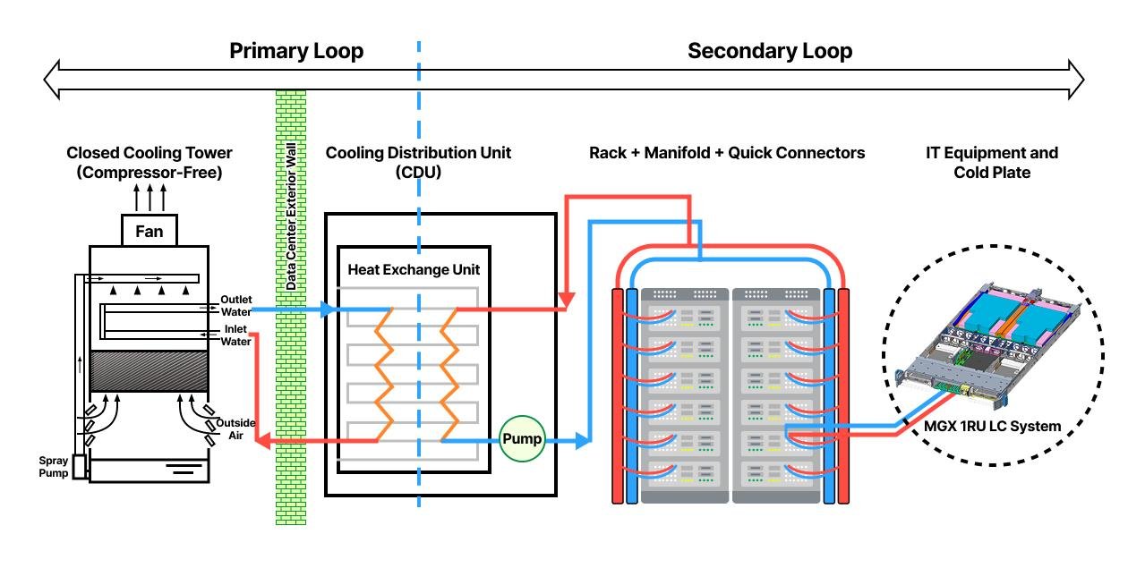
3.2 What Does a Coolant Distribution Unit (CDU) Do?
A Coolant Distribution Unit is a central component in many direct-to-chip liquid cooling systems.
Its purpose is to manage coolant circulation and, where applicable, separate the technology cooling loop from the facility cooling loop through a heat exchanger.
A CDU may include:
Circulation pumps
Heat exchanger
Filters or strainers
Temperature sensors
Pressure sensors
Flow monitoring
Control valves
Monitoring and control interfaces
Not all CDUs have identical configurations. Their design depends on the cooling architecture, required flow rate, operating pressure, coolant temperatures, heat load, and facility integration requirements.
When selecting a CDU, engineers should evaluate:
Required thermal capacity
Coolant supply and return temperatures
Flow rate
Pressure drop
Operating pressure
Heat exchanger configuration
Coolant compatibility
Pump redundancy
Monitoring and alarm functions
Service and maintenance access
An incorrectly selected CDU may restrict coolant flow, create excessive pressure drop, or fail to meet the required heat transfer conditions.
3.3 How Does Immersion Cooling Work?
Immersion cooling removes heat by placing IT equipment or selected components inside a tank filled with dielectric fluid.
Unlike direct-to-chip cooling, which transfers heat through cold plates attached to specific components, immersion cooling brings the dielectric fluid into direct contact with the immersed equipment.
There are two main configurations.
Single-phase immersion cooling
The dielectric fluid remains liquid during normal operation.
Pumps circulate the heated fluid through a heat exchanger, where heat transfers to another cooling loop.
The cooled fluid then returns to the tank.
Two-phase immersion cooling
The dielectric fluid absorbs heat and changes from liquid to vapor.
The vapor rises and transfers heat to a condenser, where it returns to liquid form.
The liquid then flows back into the tank.
Immersion cooling requires careful evaluation of fluid properties, server compatibility, tank design, maintenance procedures, and heat rejection requirements.
It should not be treated as interchangeable with direct-to-chip cooling. The two technologies have different equipment interfaces and operational requirements.
4. How Is Heat Removed From a Data Center?
Removing heat from servers is only the first stage of the cooling process.
The collected heat must eventually be transferred outside the IT environment and rejected to the surrounding atmosphere or another suitable heat sink.
This is where chillers, dry coolers, cooling towers, pumps, and heat exchangers become essential.
4.1 How Does a Data Center Chiller Work?
A chiller removes heat from a water or water-based fluid circuit and transfers it to a separate heat rejection system.
A typical vapor-compression chiller contains four major refrigeration components:
Evaporator
Compressor
Condenser
Expansion device
The basic process is:
Warm return water enters the chiller evaporator.
Refrigerant absorbs heat from the water.
The compressor raises refrigerant pressure.
Heat transfers from the refrigerant through the condenser.
The expansion device reduces refrigerant pressure.
The chilled water returns to the cooling equipment.
The chilled water may supply CRAH units, air handling equipment, or other cooling systems.
Chillers are commonly classified by how they reject heat.
Air-cooled chillers
Air-cooled chillers use outdoor air to remove heat from the refrigerant through condenser coils and fans.
They generally avoid the need for a dedicated cooling tower and condenser-water loop.
Water-cooled chillers
Water-cooled chillers transfer heat into a condenser-water circuit.
The condenser water may then reject heat through a cooling tower or another suitable heat rejection arrangement.
The choice depends on climate, water availability, plant design, energy objectives, maintenance requirements, and project economics.
4.2 How Does a Dry Cooler Work?
A dry cooler uses ambient air to remove heat from a circulating liquid through a heat exchanger.
The process is relatively straightforward:
Warm water or coolant enters the dry cooler.
Fans move ambient air across heat exchanger coils.
Heat transfers from the circulating liquid to the air.
The cooled liquid returns to the cooling system.
Dry coolers are commonly considered in data center liquid cooling infrastructure, particularly where operating temperatures allow heat rejection without mechanical refrigeration for some or all operating conditions.
Their performance depends heavily on outdoor dry-bulb temperature, fluid temperature, heat exchanger design, airflow, and required leaving-fluid conditions.
A dry cooler does not provide the same cooling capability under all ambient conditions. If the outdoor air is too warm relative to the required coolant temperature, additional cooling equipment may be necessary.
4.3 How Does a Cooling Tower Work?
A cooling tower removes heat from circulating water primarily through evaporative cooling.
Warm condenser water enters the tower and is distributed across a heat transfer surface.
Air moves through the tower, and a portion of the water evaporates. This evaporation removes heat from the remaining water.
The cooled water collects in the tower basin and returns to the condenser circuit.
Cooling towers are often used with water-cooled chillers.
Their operation requires consideration of:
Water consumption
Water treatment
Scaling and corrosion
Biological control
Drift management
Ambient wet-bulb conditions
Regular cleaning and inspection
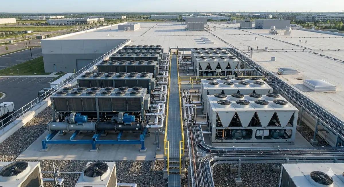
4.4 How the Main Cooling Components Work Together
A traditional chilled-water air cooling system may follow this heat transfer path:
Servers → Room air → CRAH coil → Chilled water → Chiller → Condenser water or outdoor air → Environment
A direct-to-chip liquid cooling system may follow this path:
CPU/GPU → Cold plate → Technology coolant loop → CDU heat exchanger → Facility cooling loop → Chiller or dry cooler → Environment
These examples illustrate why data center cooling should be designed as an integrated thermal system.
The cooling unit inside the server room cannot operate effectively without a suitable downstream heat rejection system.
5. How Is a Data Center Cooling System Designed and Sized?
Selecting cooling equipment requires more than matching a product’s nominal capacity to the IT electrical load.
Engineers must calculate the actual thermal load, evaluate operating conditions, and confirm that each part of the cooling system can handle its assigned heat load.
5.1 Calculate the Required Cooling Capacity
A basic starting point is to estimate the IT heat load from the electrical power consumed by the IT equipment.
For a complete facility, the design cooling load may include:
Where:
\(Q_{\text{IT}}\) = IT equipment heat load
\(Q_{\text{UPS}}\) = UPS heat losses
\(Q_{\text{Electrical}}\) = other electrical distribution losses
\(Q_{\text{Lighting}}\) = lighting heat load
\(Q_{\text{Other}}\) = other relevant heat gains
This is a simplified load accounting framework. Actual design calculations should follow the project’s engineering methodology and account for the relevant operating conditions.
Cooling capacity should also distinguish between:
Total cooling capacity: The total heat removal capability under specified conditions.
Sensible cooling capacity: The portion of cooling capacity used to reduce air temperature.
Latent cooling capacity: The portion used to remove moisture from air.
Design cooling load: The calculated heat load the system must handle under defined design conditions.
Available operating capacity: The capacity an actual unit can deliver under its specific operating conditions.
For data centers, sensible cooling is often a major part of the load, but humidity control and latent load requirements should not be ignored where applicable.
5.2 Calculate Coolant Flow Requirements for Liquid Cooling
For a liquid cooling loop, the heat transfer relationship can be expressed as:
Where:
\(Q\) = heat transferred, in kW when using consistent SI units
\(\dot{m}\) = coolant mass flow rate, in kg/s
\(c_p\) = specific heat capacity of the coolant, in kJ/(kg·K)
\(\Delta T\) = coolant temperature rise, in K
This formula helps engineers estimate the coolant mass flow required for a given heat load and temperature difference.
For example, a higher temperature difference can reduce the mass flow required for the same heat transfer, assuming the coolant properties and system constraints remain suitable.
However, the final flow rate must also account for cold plate performance, pressure drop, pump capacity, coolant properties, and server manufacturer requirements.
5.3 Evaluate Airflow Requirements
For air-cooled systems, engineers must ensure that the cooling system can deliver sufficient airflow at the required supply conditions.
Important factors include:
Rack power density
Server airflow requirements
Air temperature rise through the equipment
Supply and return air paths
Containment configuration
Fan performance
Static pressure
Air leakage and bypass airflow
A cooling unit may have sufficient nominal capacity but still fail to deliver effective cooling if airflow distribution is poor.
This is why rack-level measurements and airflow analysis are important during design and commissioning.
5.4 Plan for Redundancy and Future Expansion
Data center cooling systems must account for equipment failures and planned maintenance.
Depending on availability requirements, projects may use redundant cooling units, pumps, chillers, power supplies, or distribution paths.
Common redundancy concepts include:
N: Capacity required to support the design load
N+1: One additional capacity unit beyond the required number
2N: Two independent systems, each designed to support the required load
These configurations are not interchangeable guarantees of availability. Actual resilience depends on system topology, electrical independence, controls, distribution paths, maintenance procedures, and common-mode failure risks.
Future expansion should also be considered.
A cooling system that meets today’s requirements may become inadequate if the facility later introduces higher-density racks, new GPU platforms, or additional IT capacity.
6. How to Maintain and Troubleshoot Data Center Cooling Systems
Regular maintenance helps prevent cooling failures, maintain thermal stability, and identify performance problems before they affect IT equipment.
The maintenance program should reflect the equipment type, manufacturer instructions, operating conditions, and facility risk assessment.
6.1 Common Air Cooling Problems
Problem | Possible Causes | Recommended Checks |
|---|---|---|
Server hot spots | Poor airflow, hot-air recirculation, blocked intakes | Check server inlet temperatures and rack airflow |
Insufficient cooling | Inadequate capacity, equipment faults, high IT load | Review cooling load and unit operating status |
Uneven room temperatures | Poor air distribution or airflow balancing | Inspect supply and return paths |
High fan energy | Excessive airflow resistance or incorrect fan control | Check filters, ducts, grilles and fan settings |
Excessive humidity variation | Control issues or unsuitable operating conditions | Review humidity sensors and control settings |
Practical maintenance tasks include:
Inspecting and replacing air filters
Cleaning coils
Checking fans and motors
Inspecting refrigerant circuits where applicable
Checking chilled-water valves and flow
Verifying sensors and control sequences
Reviewing alarms and operating trends
6.2 Common Liquid Cooling Problems
Problem | Possible Causes | Recommended Checks |
|---|---|---|
Insufficient coolant flow | Pump problems, blocked filters, valve restrictions | Check flow sensors, pump status and pressure |
High coolant temperature | Excessive heat load or insufficient heat rejection | Review supply and return temperatures |
Coolant leakage | Damaged seals, loose connections, installation defects | Inspect connections and leak detection alarms |
Excessive pressure drop | Restricted piping, blocked components, incorrect design | Compare measured pressure with design conditions |
Unstable cooling performance | Control issues, variable loads, sensor faults | Review temperature, flow and control trends |
Liquid cooling maintenance may include:
Checking pump performance
Inspecting piping and connections
Monitoring coolant condition
Checking filters and strainers
Verifying pressure and flow sensors
Testing leak detection
Inspecting heat exchangers
Reviewing CDU alarms and operating data
Coolant sampling and treatment should follow the system supplier’s specifications. Operators should not assume that every liquid cooling system uses the same fluid chemistry or maintenance procedure.
6.3 Monitor Cooling Performance Continuously
A reliable monitoring strategy should collect data from the relevant cooling equipment and IT environment.
Depending on the architecture, important parameters may include:
Air cooling monitoring
Server inlet temperature
Return-air temperature
Supply-air temperature
Relative humidity where relevant
Fan speed
Cooling unit operating status
Chilled-water supply and return temperatures
Liquid cooling monitoring
Coolant supply temperature
Coolant return temperature
Flow rate
Operating pressure
Pressure differential
Pump status
Leak detection status
CDU alarms
Trend analysis can help operators identify gradual changes, such as increasing return temperatures, declining flow, filter restrictions, or cooling capacity deterioration.
Conclusion: Understanding the Complete Data Center Cooling Process
A data center cooling system works by collecting heat from IT equipment, transferring it through air or liquid cooling circuits, and ultimately rejecting that heat outside the facility.
Air-cooled systems use precision air conditioning, CRAC or CRAH units, airflow management, and chilled-water or refrigeration infrastructure.
Liquid cooling systems use cold plates or immersion tanks to absorb heat closer to IT components, with CDUs and facility cooling loops transferring the heat to chillers, dry coolers, or other heat rejection equipment.
The most suitable configuration depends on IT load, rack density, facility infrastructure, operating conditions, energy objectives, reliability requirements, and future expansion plans.
For many facilities, a combination of air cooling and liquid cooling can provide the flexibility needed to support both conventional servers and high-density AI infrastructure.
Planning a new data center or upgrading an existing cooling system?
Our equipment portfolio includes precision air conditioners, CRAC and CRAH systems, in-row cooling, rear door heat exchangers, direct-to-chip liquid cooling systems, CDUs, chillers, and dry coolers.
Click here to schedule a technical consultation for your data center cooling project. Share your IT load, rack configuration, cooling requirements, and facility conditions to begin evaluating a suitable thermal management solution.
Frequently Asked Questions
1. What are the main components of a data center cooling system?
A typical data center cooling system may include precision air conditioners, CRAC or CRAH units, pumps, fans, heat exchangers, chillers, dry coolers, cooling towers, piping, and monitoring controls. Liquid-cooled facilities may also include cold plates, CDUs, manifolds, and coolant distribution piping.
The exact equipment depends on the cooling architecture.
2. How does a data center remove heat from servers?
In an air-cooled system, server fans move air across internal components. The heated air is collected by the room cooling system, which transfers the heat to a refrigerant or chilled-water circuit.
In a liquid-cooled system, coolant absorbs heat through cold plates or immersion fluid and transfers it to a facility cooling loop.
3. What is the difference between a CRAC and a CRAH unit?
A CRAC unit typically uses a direct-expansion refrigeration system to cool air. A CRAH unit uses a chilled-water coil and generally depends on a separate chiller plant.
Both are used to deliver conditioned air to data center environments, but their cooling infrastructure and maintenance requirements differ.
4. What does a CDU do in a data center?
A Coolant Distribution Unit manages coolant circulation in a liquid cooling system. Depending on its configuration, it may provide pumping, filtration, monitoring, and heat exchange between the technology cooling loop and the facility cooling loop.
Its required capacity, flow rate, operating pressure, and coolant compatibility must match the project requirements.
5. Does a data center cooling system run continuously?
Yes. Data center cooling systems generally operate continuously because IT equipment produces heat whenever it is running. Cooling capacity and equipment operation may vary with IT load and environmental conditions, but the system must maintain suitable thermal conditions at all times.
6. How do I calculate the cooling capacity required for a data center?
Begin by estimating the heat generated by IT equipment from its electrical power consumption. Then add other relevant facility heat gains, including electrical losses, lighting, and other loads.
The final design must also account for operating conditions, sensible and latent cooling requirements, equipment performance, redundancy, and future expansion. Rack-level heat distribution should be evaluated separately from the total facility load.