Data center cooling has become increasingly difficult as IT infrastructure evolves toward higher rack power densities, GPU-intensive workloads, and more complex server configurations. Cooling systems must remove heat reliably, maintain acceptable equipment inlet conditions, support future expansion, and control energy consumption without compromising availability.
Many cooling problems are not caused by insufficient equipment capacity alone. Poor airflow management, hot-air recirculation, inadequate heat rejection, incorrect control settings, and mismatches between cooling infrastructure and IT loads can all affect thermal performance.
For data center operators, the challenge is to identify the actual limitation and select a solution that addresses the entire cooling process rather than treating individual symptoms.
This guide examines the major data center cooling challenges and solutions affecting modern IT infrastructure, including high-density rack cooling, airflow distribution, energy efficiency, liquid cooling, system reliability, and equipment selection.
1. Insufficient Cooling Capacity for Increasing IT Loads
One of the most common data center cooling challenges is maintaining sufficient cooling capacity as server installations and computing workloads increase.
Traditional facilities may have been designed around relatively moderate rack power densities. Newer AI, GPU, and high-performance computing deployments can introduce significantly higher and more concentrated heat loads.
A cooling system that previously operated reliably may become inadequate when additional servers are installed or existing racks are upgraded.
Why does insufficient cooling capacity occur?
Several factors can contribute:
IT electrical loads increase beyond the original design assumptions.
New servers have higher power consumption.
Rack power density becomes uneven across the room.
Cooling equipment loses performance because of fouled coils, restricted airflow, or mechanical deterioration.
Chillers, pumps, or heat rejection equipment cannot support the increased load.
Cooling capacity is calculated using nominal equipment ratings rather than actual operating conditions.
Another common problem is relying on average room cooling capacity. A facility may have sufficient total cooling capacity but still experience overheating in individual high-density racks.
How to assess the required cooling capacity
Start with the actual IT electrical load and identify additional heat gains within the conditioned space.
A simplified calculation is:
[
Q_{total}=Q_{IT}+Q_{electrical}+Q_{lighting}+Q_{envelope}+Q_{ventilation}
]
Where:
(Q_{IT}) is the heat generated by IT equipment.
(Q_{electrical}) is heat from electrical equipment within the conditioned area.
(Q_{lighting}) is heat from lighting and occupants.
(Q_{envelope}) is heat transferred through the building structure.
(Q_{ventilation}) is heat introduced through ventilation and infiltration.
For example, a facility with 400 kW of IT load and 30 kW of additional heat gains has a preliminary cooling load of approximately 430 kW.
This figure is not automatically the required installed cooling capacity. Final equipment selection must consider design conditions, sensible and latent loads, equipment performance, airflow distribution, redundancy, and future expansion.
Rack-level assessment is also essential. Record the power consumption and inlet temperatures of individual racks to identify localized cooling requirements.
Practical cooling solutions
Depending on the actual constraint, possible solutions include:
Replacing undersized or deteriorated precision air-conditioning units.
Adding CRAC or CRAH capacity.
Introducing in-row cooling for selected high-density rack groups.
Upgrading chillers, pumps, or heat rejection equipment.
Installing rear door heat exchangers.
Introducing direct-to-chip liquid cooling for compatible high-density servers.
The key is to determine whether the bottleneck exists at room level, rack level, or within the central cooling plant.
2. Uneven Airflow Distribution and Server Rack Hot Spots
Insufficient cooling capacity is not the only reason servers overheat. Poor airflow management can cause hot spots even when the facility has adequate total cooling output.
The problem often occurs when cold supply air mixes with hot exhaust air before reaching server inlets, or when cooling airflow is distributed unevenly across the room.
Common causes of data center hot spots
Hot-air recirculation
Hot exhaust air from server racks returns to the front of the racks instead of reaching the cooling unit’s return-air path. This raises server inlet temperatures.
Bypass airflow
Cold air travels through unused openings, cable penetrations, or poorly sealed rack spaces without passing through IT equipment. Cooling capacity is wasted because the supply air does not reach the intended heat source.
Uneven floor air distribution
In raised-floor environments, incorrect floor tile placement, insufficient underfloor pressure, obstructions, or cable congestion can restrict cold-air delivery to particular racks.
High rack power density
A rack with significantly greater power consumption than surrounding racks may require more airflow than the existing room-level cooling arrangement can provide.
How to improve data center airflow management
Start by measuring temperatures at the server inlets rather than relying solely on a room thermostat.
For important or high-density racks, measure at multiple vertical positions to identify temperature differences between the top, middle, and bottom sections.
Practical improvements include:
Install blanking panels in unused rack spaces.
Seal unnecessary openings in floors and cable pathways.
Separate hot and cold air paths.
Correct the positioning of perforated floor tiles where applicable.
Remove obstructions from supply and return airflow paths.
Balance airflow according to rack-level demand.
Review fan operation and cooling-unit control settings.
Cold aisle and hot aisle containment
Containment systems reduce the mixing of supply and exhaust air.
Cold aisle containment encloses the cold-air supply area in front of server racks. Hot aisle containment encloses the hot exhaust area behind the racks.
| Feature | Cold aisle containment | Hot aisle containment |
|---|---|---|
| Main objective | Protect cold supply air | Capture hot exhaust air |
| Enclosed area | Cold aisle | Hot aisle |
| Main benefit | More controlled server inlet conditions | More controlled hot-air return |
| Key design consideration | Cold-air delivery and room pressure | Hot-air return path and heat removal |
Neither arrangement is universally superior. The choice depends on the existing cooling architecture, room layout, fire protection strategy, ceiling configuration, and operational requirements.
For facilities with persistent localized hot spots, containment and airflow correction may be more effective than immediately installing additional cooling units.
3. High-Density GPU and AI Server Cooling
AI training, inference, and high-performance computing introduce new thermal management requirements.
GPU servers can concentrate substantial electrical power and heat within a relatively small rack footprint. This creates challenges for conventional room-level air cooling, particularly when rack density increases faster than the original cooling infrastructure can accommodate.
Why traditional air cooling can become difficult
Air cooling transfers heat from IT components into server exhaust air, which must then be removed by the facility cooling system.
As component power increases, the system may require greater airflow, smaller temperature differences, or more effective heat transfer.
Potential limitations include:
Insufficient airflow through densely populated racks.
High fan power requirements.
Uneven air distribution within servers.
Localized component temperatures exceeding acceptable limits.
Limited room for additional cooling units.
Increased load on the chilled-water or heat rejection system.
The actual cooling requirement depends on server architecture, rack power, component design, airflow characteristics, and operating conditions. Not every AI rack has the same thermal requirements.
Cooling solutions for high-density infrastructure
In-row cooling
In-row cooling units are installed close to server racks and provide localized cooling. They can shorten the airflow path and help support rack groups with higher thermal loads.
This approach can be suitable for facilities that need additional cooling in selected areas without replacing the entire room-level cooling system.
Rear door heat exchangers
Rear door heat exchangers remove heat from server exhaust air as it leaves the rack.
They can reduce the heat released into the surrounding room and help support higher-density deployments. Their suitability depends on rack compatibility, heat exchanger configuration, water conditions, and maintenance requirements.
Direct-to-chip liquid cooling
Direct-to-chip cooling uses cold plates attached to supported high-power components, transferring heat into a liquid circuit.
A typical system includes cold plates, coolant piping, pumps, controls, and a coolant distribution unit (CDU).
It is particularly relevant for compatible GPU and HPC servers where component heat loads are difficult to manage with air cooling alone.
However, direct-to-chip cooling does not necessarily remove all heat from the server room. Components not connected to cold plates may continue to reject heat into the air.
Air cooling vs. liquid cooling for high-density servers
| Factor | Air cooling | Direct-to-chip liquid cooling |
|---|---|---|
| Heat transfer medium | Air | Liquid coolant |
| Main heat removal path | Server airflow and room cooling | Cold plates and liquid circuit |
| Typical application | General-purpose IT and supported rack densities | Compatible high-density GPU and HPC servers |
| Infrastructure requirements | Air handlers, CRAC/CRAH, airflow paths | CDUs, piping, compatible servers, heat rejection |
| Main design concern | Airflow and inlet temperature | Coolant flow, temperature, pressure, compatibility |
| Operational risks | Hot spots and airflow imbalance | Leakage, coolant quality, flow interruption |
The most suitable solution may be a hybrid system that combines liquid cooling for selected high-power components with air cooling for residual room loads.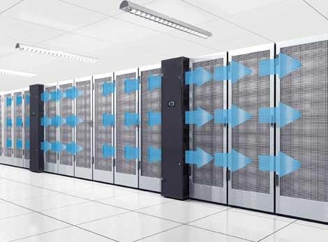
4. High Cooling Energy Consumption and Poor System Efficiency
Cooling can account for a significant portion of a data center’s non-IT energy consumption. Inefficient cooling operation increases operating costs and can reduce the effectiveness of energy management efforts.
However, high cooling energy consumption does not always mean that the equipment itself is inefficient. Poor control strategies, excessive airflow, unsuitable temperature settings, and inefficient heat rejection can also contribute.
Common causes of excessive cooling energy use
Overcooling
Cooling units may maintain unnecessarily low supply-air temperatures even when server inlet conditions are already within the required operating range.
Excessive fan operation
Fans running at unnecessarily high speeds consume additional power. Poor airflow design may also force fans to work harder to overcome system resistance.
Inefficient chiller operation
Chillers may operate inefficiently because of inappropriate water temperatures, poor load matching, fouled heat-transfer surfaces, or unsuitable equipment sequencing.
Simultaneous heating and cooling
Poorly coordinated controls can cause different parts of a facility to heat and cool at the same time, wasting energy.
Poor heat rejection
Dirty cooling tower fill, restricted heat exchangers, inadequate water flow, or poorly maintained dry coolers can reduce heat rejection performance.
Practical solutions to improve cooling efficiency
1. Optimize temperature setpoints
Review server inlet temperatures and equipment operating limits before adjusting supply-air settings. Avoid unnecessarily low temperature targets.
2. Use variable-speed equipment where appropriate
Variable-speed fans and pumps can adjust output to actual demand. Their suitability depends on equipment design, minimum operating requirements, and control compatibility.
3. Improve airflow management
Containment, blanking panels, and sealing bypass openings can improve the effectiveness of existing cooling capacity.
4. Evaluate economizer operation
Air-side or water-side economization may reduce mechanical cooling demand when outdoor conditions and environmental requirements permit.
5. Improve heat rejection
Inspect chillers, cooling towers, dry coolers, pumps, and heat exchangers. A problem in the heat rejection system can reduce the performance of the entire cooling chain.
How to evaluate cooling efficiency
Power Usage Effectiveness (PUE) is calculated as:
[
PUE=\frac{Total\ Facility\ Energy}{IT\ Equipment\ Energy}
]
PUE helps measure overall facility energy overhead, but it does not independently identify the source of cooling inefficiency.
For practical cooling optimization, also monitor:
Cooling equipment electrical consumption.
Chiller power.
Pump and fan power.
Cooling output.
Server inlet temperatures.
Water supply and return temperatures.
Equipment operating hours.
Cooling system performance under comparable IT loads.
Compare measurements under similar operating conditions before and after changes. Otherwise, workload and weather differences can make performance comparisons misleading.
5. Cooling System Reliability, Redundancy, and Maintenance
Cooling system reliability is essential because a cooling failure can cause server temperatures to rise rapidly, potentially leading to equipment throttling, shutdowns, or service interruption.
Modern data centers must consider not only normal operation but also equipment failure, maintenance activities, power interruptions, and changes in cooling demand.
Common reliability challenges
Aging compressors, pumps, and fans.
Refrigerant leakage or abnormal operating pressures.
Blocked filters and dirty heat exchangers.
Unstable control systems or inaccurate sensors.
Chilled-water supply interruptions.
Insufficient standby cooling capacity.
Shared components that create single points of failure.
Inadequate maintenance access.
Design cooling redundancy around the entire system
Common redundancy architectures include:
N: Capacity required to support the design load, without additional standby capacity.
N+1: Required capacity plus one additional unit or component.
2N: Two independent systems, each designed to support the required load.
These configurations are not interchangeable, and the appropriate architecture depends on availability requirements, cost, maintenance strategy, and system design.
Redundancy must also be considered across the complete cooling path. Multiple CRAC units do not guarantee resilience if they share a vulnerable electrical supply, pump, control system, or heat rejection component.
Establish a preventive maintenance program
A practical maintenance program should cover:
| Equipment | Maintenance considerations |
|---|---|
| CRAC and precision AC | Filters, coils, fans, refrigerant circuits, condensate drainage |
| CRAH units | Filters, coils, valves, fans, chilled-water connections |
| Chillers | Refrigeration circuit, heat exchangers, controls, operating records |
| Pumps | Mechanical seals, vibration, flow, pressure, motor condition |
| Cooling towers | Water treatment, fill, fans, drift eliminators, heat-transfer surfaces |
| Dry coolers | Coil cleanliness, fans, controls, fluid connections |
| Liquid cooling systems | Coolant quality, flow, pressure, filters, leak detection |
| CDUs | Pumps, heat exchangers, controls, sensors, alarms |
Maintenance intervals should follow equipment documentation, operating conditions, and site procedures rather than an arbitrary universal schedule.
6. How to Select the Right Data Center Cooling Solution
Selecting cooling equipment requires a project-specific assessment. A solution that works well in one facility may be unsuitable for another because of differences in rack density, climate, existing infrastructure, floor space, and reliability requirements.
Match the technology to the actual problem
| Data center challenge | Potential solution | Key information to verify |
|---|---|---|
| Insufficient room cooling | Precision AC, CRAC, or CRAH upgrade | Actual load and equipment performance |
| Localized rack hot spots | In-row cooling or airflow optimization | Rack inlet temperatures and airflow |
| Hot-air recirculation | Cold aisle or hot aisle containment | Room layout and return-air paths |
| High rack heat load | Rear door heat exchanger | Rack compatibility and water conditions |
| High-density GPU servers | Direct-to-chip liquid cooling | Server compatibility and coolant requirements |
| Insufficient heat rejection | Chiller, cooling tower, or dry cooler upgrade | Outdoor conditions and plant capacity |
| High energy consumption | Control optimization and system upgrades | Equipment-level energy measurements |
| Reliability concerns | Redundancy and maintenance improvements | Failure scenarios and shared components |
Information required before purchasing cooling equipment
Before requesting a quotation, prepare:
IT load: Current and planned IT power consumption in kW.
Rack configuration: Number of racks, dimensions, and individual rack power densities.
Environmental conditions: Server inlet temperatures, humidity, and identified hot spots.
Existing cooling equipment: Equipment type, model, capacity, age, and operating condition.
Cooling infrastructure: Chilled-water temperatures and flow, refrigerant arrangements, piping, and heat rejection equipment.
Site conditions: Available installation space, electrical supply, access routes, and maintenance clearances.
Reliability requirements: Required redundancy and maintenance arrangements.
Future expansion: Expected IT load and rack density changes.
For liquid-cooling projects, also provide server liquid-cooling specifications, coolant requirements, CDU interface information, piping routes, and heat rejection requirements.
What should buyers evaluate when choosing a cooling equipment supplier?
A supplier should be able to provide clear technical information relevant to the proposed equipment and project.
Important evaluation criteria include:
Cooling capacity under specified operating conditions.
Airflow or liquid-side performance data.
Equipment dimensions and installation requirements.
Electrical and mechanical interfaces.
Control and monitoring compatibility.
Maintenance requirements.
Technical documentation.
Warranty terms and spare parts arrangements.
Delivery and project coordination.
For larger projects, confirm whether the proposed equipment can integrate with the existing MEP design and facility control architecture.
A technically suitable product is only one part of a successful cooling solution. Compatibility, installation planning, commissioning, and long-term maintenance also matter.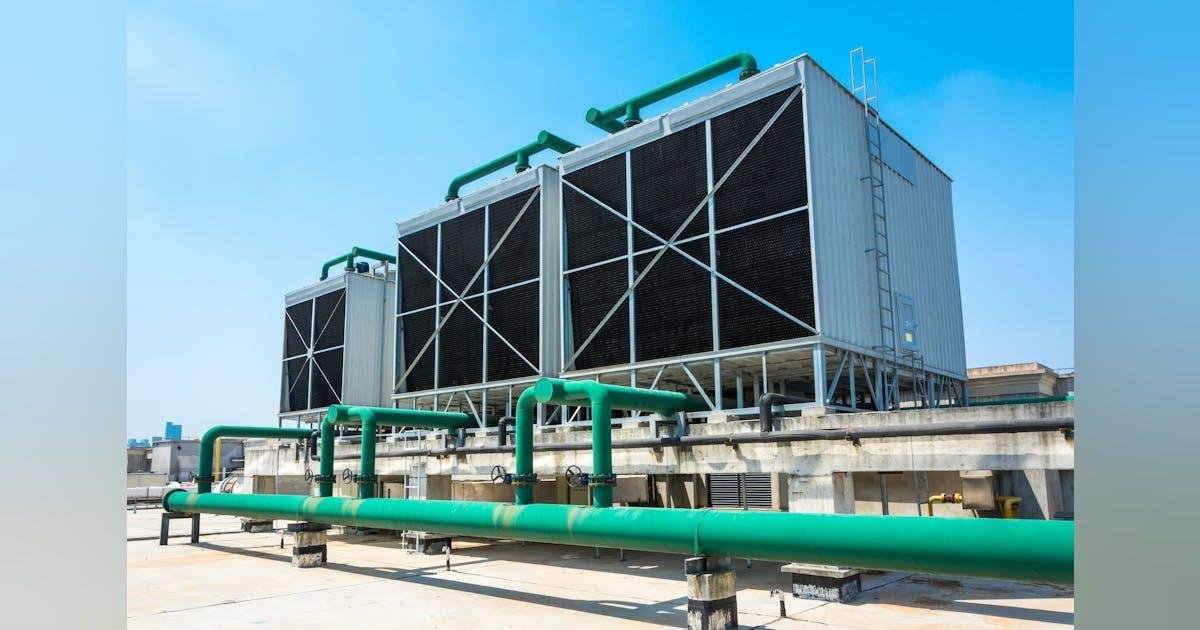
Frequently Asked Questions
1. What are the most common data center cooling challenges?
The most common challenges include insufficient cooling capacity, uneven airflow, server rack hot spots, high-density GPU heat loads, excessive cooling energy consumption, inadequate heat rejection, and insufficient system redundancy. The underlying cause should be identified before selecting equipment.
2. How can data center hot spots be prevented?
Measure server inlet temperatures at different rack heights, correct hot-air recirculation, seal bypass openings, install blanking panels, and optimize supply and return airflow. For high-density rack groups, in-row cooling or rear door heat exchangers may be appropriate.
3. Is air cooling still suitable for modern data centers?
Yes. Air cooling remains suitable for many conventional IT environments and for equipment designed to operate within its capabilities. However, higher rack densities may require improved airflow management, localized cooling, or liquid cooling for selected components.
4. When should a data center use liquid cooling?
Liquid cooling should be considered when supported server components generate heat loads that are difficult to manage effectively through air cooling alone. Direct-to-chip cooling is particularly relevant for compatible GPU and HPC infrastructure. Server compatibility, coolant conditions, CDU configuration, and heat rejection must be assessed.
5. How can a data center reduce cooling energy consumption?
Start by measuring equipment-level energy consumption and checking actual server inlet temperatures. Potential improvements include airflow optimization, appropriate temperature setpoints, variable-speed fans and pumps, improved chiller control, and suitable economizer operation.
6. What information is needed to select a data center cooling system?
Important information includes IT load, rack quantity and power density, required cooling capacity, operating temperatures, existing equipment, chilled-water conditions where applicable, outdoor design conditions, available space, electrical supply, and redundancy requirements.
Conclusion
Modern data center cooling challenges cannot be solved by simply increasing the number or rated capacity of cooling units. Effective thermal management requires coordination between IT equipment, rack airflow, room cooling, liquid cooling where applicable, heat rejection, controls, and maintenance.
For conventional facilities, improvements to precision air conditioning, CRAC and CRAH systems, airflow management, and containment may address many existing problems. For higher-density AI and GPU infrastructure, in-row cooling, rear door heat exchangers, and direct-to-chip liquid cooling may provide additional heat removal capacity.
The right solution depends on measured operating conditions and the facility’s future requirements.
If you are planning a new cooling installation or evaluating improvements to an existing data center, contact our team to discuss your IT load, rack configuration, cooling requirements, and equipment selection. Request a technical consultation for a cooling solution aligned with your project conditions.