Data center cooling system design is not simply a matter of selecting air conditioners with enough cooling capacity. A reliable design must control heat at the rack level, maintain suitable environmental conditions, distribute cooling effectively, reject heat under local outdoor conditions, and keep critical equipment operating during maintenance or component failures.
For facility owners and engineering teams, the challenge is to develop a cooling architecture that meets current IT requirements without creating unnecessary energy consumption, operational complexity, or expensive expansion constraints.
The right approach begins with the actual heat load and rack layout, then moves through cooling architecture, equipment selection, airflow or liquid distribution, redundancy, controls, and commissioning. Each decision affects the performance of the complete thermal management system.
This guide explains the main engineering considerations involved in designing a data center cooling system, including traditional air cooling, high-density applications, and liquid cooling for AI infrastructure.
1. Define the Cooling Requirements Before Selecting Equipment
The first step in data center cooling system design is to establish the facility’s thermal requirements. Equipment should not be selected based only on the building’s floor area or the total number of server racks.
The cooling requirement depends on how much heat the facility generates, where that heat is concentrated, and the environmental conditions under which the system must operate.
Calculate the total data center cooling load
Most of the electrical power consumed by IT equipment eventually becomes heat inside the data center. Therefore, the IT electrical load provides the starting point for estimating the cooling requirement.
A preliminary total heat-load calculation can be expressed as:
Where:
\(Q_{\text{IT}}\): Heat generated by servers, storage systems, and network equipment.
\(Q_{\text{electrical}}\): Heat from UPS systems, transformers, power distribution equipment, and other electrical losses located within the conditioned space.
\(Q_{\text{lighting}}\): Heat generated by lighting.
\(Q_{\text{envelope}}\): Heat transfer through walls, roofs, floors, and other building surfaces.
\(Q_{\text{ventilation}}\): Heat and moisture loads associated with outdoor air and infiltration.
The exact calculation should reflect the facility’s mechanical and electrical arrangement. For example, UPS equipment located in a separate electrical room should not automatically be included in the server-room heat load.
Illustrative calculation
Assume a facility has:
Load source | Estimated heat load |
|---|---|
IT equipment | 500 kW |
Electrical losses within conditioned space | 20 kW |
Lighting and occupancy | 5 kW |
Building envelope and ventilation | 15 kW |
Total estimated heat load | 540 kW |
The preliminary cooling load is approximately 540 kW.
Useful unit conversions include:
1 kW ≈ 3,412 BTU/h
1 refrigeration ton (RT) ≈ 3.517 kW
Therefore:
This is an estimated thermal load, not a final equipment selection. The installed cooling capacity must account for actual equipment performance, operating conditions, redundancy, and the intended design philosophy.
Evaluate rack power density, not just total IT load
Two data centers can have the same total IT load but require very different cooling arrangements.
Consider the difference between:
A 500 kW facility with relatively low-density racks distributed across a large room.
A 500 kW facility with a smaller number of high-density GPU racks.
The second facility may experience concentrated heat loads that conventional room-level air conditioning cannot handle effectively.
Before selecting equipment, establish:
Total IT load and expected growth.
Number of racks and planned rack locations.
Average and maximum rack power density.
Server airflow direction and equipment intake requirements.
Locations of high-density GPU or HPC racks.
Whether future direct-to-chip or immersion cooling is anticipated.
A rack-level load map is particularly useful because it identifies where additional cooling capacity or localized heat removal may be necessary.
Establish environmental and operating conditions
Cooling equipment must be selected for the actual project environment.
Important inputs include:
Outdoor design dry-bulb and wet-bulb temperatures, where applicable.
Required server inlet temperature and humidity conditions.
Available chilled-water supply and return temperatures.
Water availability and quality.
Available electrical supply.
Altitude, dust, corrosion, and other environmental conditions.
Equipment-room dimensions and installation constraints.
For international projects, climate conditions can substantially affect the selection of chillers, dry coolers, cooling towers, and economizer systems.
2. Select the Right Data Center Cooling Architecture
Once the load and operating requirements are established, the next decision is the cooling architecture.
A typical data center cooling system includes several interconnected stages:
Heat is removed from servers and other IT equipment.
Cooling units collect or transfer the heat.
Air or a liquid coolant transports the heat through the system.
Chillers or other heat-rejection equipment transfer the heat to the outdoor environment.
Controls regulate temperatures, flow rates, and equipment operation.
A failure or capacity limitation in any stage can affect the entire cooling system.
Precision air conditioning, CRAC, and CRAH systems
Precision cooling systems are designed to provide controlled temperature and humidity conditions for IT environments.
Two common equipment categories are CRAC and CRAH.
Equipment | Typical cooling method | Main characteristics | Common application |
|---|---|---|---|
CRAC | Direct expansion (DX) | Uses a refrigeration circuit to cool and dehumidify air | Small and medium data centers, server rooms |
CRAH | Chilled water | Uses a cooling coil supplied by a chilled-water system | Larger facilities with central chilled-water plants |
Precision air conditioner | DX or chilled water, depending on configuration | Designed for controlled IT-room environmental conditions | Data centers and critical equipment rooms |
In-row cooling | DX or chilled water, depending on model | Places cooling close to heat-generating racks | High-density or localized cooling zones |
CRAC and CRAH should not be treated as interchangeable terms. A CRAC typically uses a DX refrigeration system, while a CRAH generally uses chilled water supplied by an external plant.
The choice depends on facility scale, available infrastructure, operating conditions, maintenance strategy, and lifecycle cost.
In-row cooling and rear-door heat exchangers
When heat is concentrated in particular racks, cooling closer to the source can improve heat removal.
In-row cooling systems are installed between or near server racks. They draw in hot exhaust air and supply cooled air close to the equipment intake.
They can be useful when:
Rack density varies significantly across the room.
Traditional room cooling creates localized hot spots.
The facility needs to expand cooling capacity in stages.
Airflow paths need to be shortened.
Rear-door heat exchangers transfer heat from server exhaust air into a liquid circuit through a heat exchanger mounted at the rear of the rack.
Their suitability depends on rack compatibility, available water temperatures, flow requirements, pressure drop, and the facility’s heat-rejection arrangement.
They can reduce the amount of heat released into the room, but they do not automatically eliminate the need for room-level cooling. Residual heat from other equipment and uncollected server heat still needs to be addressed.
Direct-to-chip and immersion cooling
AI servers and high-performance computing systems can create rack-level thermal loads that are difficult to manage with conventional air cooling alone.
Two important liquid cooling approaches are direct-to-chip cooling and immersion cooling.
Direct-to-chip liquid cooling circulates coolant through cold plates attached to heat-generating components, such as CPUs and GPUs. A coolant distribution unit (CDU) manages heat transfer between the technology cooling loop and the facility water system, depending on the selected configuration.
Immersion cooling places compatible IT hardware in a dielectric liquid. Heat transfers from the components into the fluid and is then removed through an appropriate heat-exchange and heat-rejection system.
Cooling method | How heat is removed | Key design considerations |
|---|---|---|
Traditional air cooling | Air passes through or around IT equipment | Airflow, containment, rack density, inlet temperature |
Rear-door heat exchanger | Liquid removes heat from rack exhaust air | Rack compatibility, water temperature, flow and pressure drop |
Direct-to-chip | Coolant circulates through component cold plates | CDU configuration, coolant compatibility, flow, pressure, leak detection |
Immersion cooling | IT equipment transfers heat directly into dielectric fluid | Hardware compatibility, fluid management, maintenance, heat rejection |
Liquid cooling is not automatically a complete replacement for air cooling. Power supplies, memory, storage, networking equipment, and other components may still require air-side heat removal, depending on the server design.
For many facilities, a hybrid air-and-liquid cooling architecture is a practical option.
3. Design Airflow and Cooling Distribution
Selecting sufficient cooling capacity does not guarantee that servers will receive enough cooling. Air must reach the equipment intakes at the required temperature and flow rate, while hot exhaust air must be removed without recirculating into the cold side.
Poor airflow management is a common reason that a data center experiences hot spots even when the installed cooling capacity appears adequate.
Use hot aisle and cold aisle arrangements
A hot aisle/cold aisle layout aligns server racks so that their cold-air intakes face one another and their hot-air exhausts face one another.
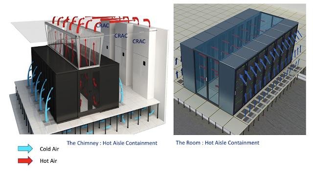


Cooling units deliver conditioned air to the cold aisle.
Servers draw air through their front intakes.
Heated air exits through the rear of the racks.
The hot aisle collects exhaust air for return to the cooling system.
This arrangement helps reduce the mixing of hot and cold air.
Cold aisle containment encloses the cold aisle to help keep supply air available to server intakes. Hot aisle containment encloses the hot aisle to capture exhaust air and direct it toward the cooling units.
Neither arrangement is universally better. The choice depends on the room layout, cooling architecture, ceiling or raised-floor configuration, fire protection, cable routing, and maintenance access.
Check airflow volume and distribution
Air cooling performance depends on both temperature and airflow volume.
For a simplified sensible heat calculation:
Where:
\(Q\): Sensible heat transfer rate.
\(\rho\): Air density.
\(c_p\): Specific heat capacity of air.
\(\dot V\): Volumetric airflow rate.
\(\Delta T\): Temperature difference between return and supply air.
This relationship helps engineers understand why a cooling unit with adequate nominal capacity may still fail to cool a rack effectively: the airflow may be insufficient or poorly distributed.
Check the following during design and commissioning:
Whether the supply airflow reaches every rack intake.
Whether cable openings and unused floor cutouts allow bypass airflow.
Whether hot exhaust air can recirculate into cold aisles.
Whether rack blanking panels are installed where required.
Whether cooling-unit airflow matches the room’s actual resistance and layout.
Whether raised-floor pressure and perforated tile locations are appropriate, if a raised floor is used.
Avoid assuming that increasing fan speed will solve every hot spot. The underlying problem may be bypass airflow, poor containment, blocked server intakes, or an unsuitable rack arrangement.
Place temperature sensors at meaningful locations
A single room thermostat cannot reliably represent the thermal conditions of an entire data center.
Temperature monitoring should focus on server inlet conditions, with sensors positioned at representative rack locations. For larger or unevenly loaded facilities, measurements at multiple rack heights can help identify vertical temperature differences.
Useful monitoring points include:
Server rack front inlet, at lower, middle, and upper levels where appropriate.
Cooling-unit supply and return air.
Hot aisle temperatures.
Chilled-water supply and return.
Critical liquid-cooling supply and return points.
The objective is to identify the conditions experienced by IT equipment, not simply to maintain a convenient room-average temperature.
4. Design the Chilled-Water and Heat-Rejection System
For chilled-water data center cooling systems, the cooling plant and distribution network must be designed as part of the complete thermal system.
A CRAH unit may have sufficient nominal capacity, for example, but its actual performance depends on chilled-water temperature, flow rate, coil characteristics, and the conditions of the air passing through it.
Select an appropriate chiller configuration
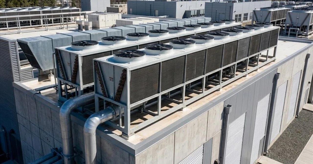
Data center cooling plants commonly use air-cooled or water-cooled chillers.


System | Heat-rejection method | Main considerations |
|---|---|---|
Air-cooled chiller | Rejects heat directly to outdoor air through air-cooled condenser coils | Outdoor dry-bulb temperature, available space, fan energy, sound |
Water-cooled chiller | Rejects heat through condenser water, commonly connected to a cooling tower | Water availability, tower operation, water treatment, maintenance |
Dry cooler | Transfers heat from a fluid loop to outdoor air | Ambient temperature, required fluid temperature, heat-exchanger approach |
Cooling tower | Rejects heat through evaporative cooling | Wet-bulb temperature, water consumption, water treatment, local regulations |
An air-cooled chiller can simplify the water-side infrastructure, but its capacity and efficiency are affected by outdoor air temperature.
A water-cooled chiller can offer advantages under suitable operating conditions, but the full system also requires condenser-water pumps, cooling towers, water treatment, and additional maintenance.
A dry cooler may support an economizer or free-cooling arrangement when outdoor conditions permit. However, it cannot be assumed to replace a chiller throughout the year. Its suitability depends on outdoor temperature, required fluid temperature, heat-exchanger approach, and the operating hours available for free cooling.
Calculate chilled-water flow requirements
A preliminary water-side heat-transfer calculation is:
Where:
\(Q\): Heat transferred by the water.
\(F\): Water flow rate.
\(\Delta T\): Water temperature difference between supply and return.
Rearranging:
For example, if a water loop must transfer 500 kW with a 5°C temperature difference:
This is a simplified estimate. Final hydraulic design must account for fluid properties, actual operating temperatures, equipment pressure drops, pipe sizing, pump head, control valves, and the required operating conditions of each cooling unit.
Design the distribution network for maintainability
A chilled-water system includes more than chillers and cooling coils. Its performance also depends on:
Supply and return piping.
Primary and secondary pumps, where applicable.
Control and isolation valves.
Strainers and filters.
Expansion and pressurization arrangements.
Water treatment and fluid-quality management.
Flow measurement and temperature sensors.
Hydraulic balancing and differential-pressure control.
The distribution network should allow individual units to be isolated for maintenance without unnecessarily disrupting the rest of the facility.
For phased projects, reserve space and connection points for future chillers, pumps, cooling units, and pipework. Expansion provisions should be included in the original design rather than added after the plant room becomes congested.
5. Integrate Liquid Cooling for High-Density and AI Data Centers
High-density GPU deployments create a different set of design requirements from conventional server rooms. The cooling system must manage concentrated component heat, fluid distribution, equipment compatibility, and the interaction between the technology cooling loop and the facility cooling infrastructure.
A liquid cooling design should begin with the server manufacturer’s requirements and the selected cooling architecture, not with an assumed standard rack capacity.
Understand the role of the CDU
A Coolant Distribution Unit manages coolant circulation and heat transfer between cooling circuits in many direct-to-chip installations.


Depending on its design, a CDU may include heat exchangers, pumps, filters, sensors, controls, and other fluid-management components.
Before selecting a CDU, establish:
Required heat-transfer capacity under project operating conditions.
Primary and secondary loop temperatures.
Required coolant flow rate.
Pressure drop across the complete circuit.
Coolant type and material compatibility.
Connection sizes and piping arrangement.
Pump redundancy and serviceability.
Leak detection and alarm integration.
Monitoring and control interfaces.
CDUs do not all have identical configurations. Some use facility water to cool a separate technology coolant loop, while other arrangements differ in pumping, heat-exchange, or integration approach.
The supplier’s technical documentation must be checked against the actual server and facility requirements.
Address liquid-loop reliability and leakage risks
Liquid cooling introduces maintenance and operational requirements that are different from those of conventional air cooling.
A suitable design should consider:
Compatible piping, seals, hoses, fittings, and heat-exchanger materials.
Coolant quality and filtration requirements.
Pressure and flow monitoring.
Leak detection around racks, manifolds, and connections.
Isolation valves and service procedures.
Condensation risk at cold surfaces.
Fluid sampling, replacement, and maintenance requirements where specified.
The coolant supply temperature must be assessed against the room’s dew point and the temperature of exposed components. If a surface falls below the surrounding air’s dew point, condensation may occur.
A hybrid cooling system should also account for heat that is not captured by the liquid circuit. Depending on the server design, room-level precision air conditioning may still be required for residual heat and non-liquid-cooled equipment.
6. Build Redundancy, Controls, and Monitoring Into the Design
A data center cooling system must remain manageable during routine maintenance and respond appropriately when equipment fails.
Redundancy should be defined at the system level rather than by simply adding spare cooling units.
Choose an appropriate redundancy strategy
Common design approaches include:
N: Installed capacity meets the calculated design requirement, with no additional capacity beyond that requirement.
N+1: One additional capacity unit is provided beyond the number required to meet the design load.
2N: Two independent systems are each designed to support the required load, subject to the actual independence of their infrastructure.
The appropriate strategy depends on the facility’s availability objectives, budget, risk tolerance, maintenance plan, and operational requirements.
A design review should examine the complete cooling path, including:
Chillers and heat-rejection equipment.
Pumps and power supplies.
Distribution piping and valves.
CRAH, CRAC, or in-row units.
CDUs and liquid-cooling loops.
Control systems and sensors.
A system with redundant chillers may still have a single point of failure in a common pump, electrical supply, control panel, or distribution header.
Design controls around actual operating conditions
An effective control system should coordinate cooling equipment instead of allowing individual units to operate without considering the overall plant.
Depending on the architecture, control functions may include:
Chiller staging and sequencing.
Pump speed control.
Cooling-unit fan speed regulation.
Supply-air or supply-water temperature control.
Differential-pressure control.
CDU flow and temperature monitoring.
Alarm generation and escalation.
Equipment status and fault monitoring.
Monitoring should provide enough information to distinguish between a capacity problem, a distribution problem, and a control problem.
For example, a rising rack inlet temperature could result from insufficient cooling capacity, poor airflow, a blocked intake, or a cooling-unit fault. Temperature data alone may not identify the cause. Airflow, equipment status, and supply and return conditions should also be evaluated.
Commission the complete system
Commissioning should verify that the installed system performs as intended under normal and abnormal operating conditions.
A practical commissioning checklist includes:
Verify equipment installation and electrical connections.
Confirm chilled-water or coolant flushing, cleaning, and treatment requirements.
Test pumps, fans, valves, and flow-control devices.
Verify temperature, pressure, and flow sensor readings.
Test control sequences and equipment staging.
Confirm alarms and monitoring-system integration.
Test planned redundancy and failure-response sequences.
Verify rack inlet conditions under representative IT loads.
Document operating parameters and maintenance procedures.
Do not assume that equipment operating individually proves that the integrated system will perform correctly. The full cooling chain must be tested.
7. Improve Energy Efficiency and Plan for Future Expansion
Cooling equipment selection affects both initial investment and long-term operating costs. A design with excessive installed capacity or poorly coordinated controls can consume unnecessary energy, particularly when the facility operates below its maximum IT load.
Evaluate the complete cooling system
Energy efficiency should be assessed across the cooling plant and distribution network.
Relevant considerations include:
Chiller performance at actual operating temperatures and part-load conditions.
Pump and fan power.
Cooling-unit airflow requirements.
Variable-speed control where appropriate.
Economizer operating hours.
Cooling tower water consumption, if applicable.
Filter and heat-exchanger pressure drop.
Control strategies and equipment sequencing.
PUE (Power Usage Effectiveness) is a facility-level metric:
A lower PUE indicates that a smaller proportion of total facility energy is used outside IT equipment. However, PUE alone does not identify which cooling component is inefficient. Cooling energy should also be measured and analyzed at the subsystem level.
Avoid selecting equipment solely by comparing nominal cooling capacity or rated efficiency. Compare performance under the project’s actual outdoor conditions, water temperatures, load profile, and operating schedule.
Make the design expandable
A data center’s cooling requirements may change as servers are replaced, rack density increases, or AI workloads are introduced.
A scalable design should consider:
Reserved plant-room space.
Future chiller and dry-cooler installation areas.
Pipework and electrical distribution capacity.
Space for additional CRAH, CRAC, or in-row units.
Potential CDU locations and liquid-cooling connections.
Service access and equipment replacement routes.
Controls and monitoring capacity for future equipment.
Where expansion is planned in phases, install only the capacity justified by the initial operating requirement while ensuring that future stages can be integrated without major disruption.
The design should also distinguish between reserving space and installing equipment. Leaving a physical expansion route may be more economical than purchasing all future cooling capacity at the beginning of a project.
8. Common Data Center Cooling System Design Mistakes
Even when individual components are correctly selected, weaknesses in the overall design can lead to poor operating performance.
Common mistake | Why it causes problems | Recommended approach |
|---|---|---|
Sizing cooling equipment only from total IT load | Ignores non-IT heat gains and rack-level concentration | Calculate total heat load and map rack power density |
Selecting equipment by nominal capacity alone | Actual output varies with operating conditions | Check performance at project-specific temperatures and flow rates |
Ignoring airflow management | Creates bypass airflow, recirculation, and hot spots | Design containment and verify rack inlet conditions |
Oversizing equipment excessively | Can increase capital cost and create inefficient part-load operation | Match installed capacity to load profile and expansion strategy |
Treating redundancy as spare cooling units only | Common pumps, power supplies, or controls may remain single points of failure | Review the complete cooling path and failure scenarios |
Adding liquid cooling without checking compatibility | May create problems with coolant, pressure, flow, and connections | Confirm server, CDU, and facility-loop requirements together |
Delaying expansion planning | Leaves insufficient space or infrastructure for additional equipment | Reserve plant space, pipe connections, electrical capacity, and service access |
Skipping integrated commissioning | Individual equipment may work while the complete system does not | Test controls, alarms, operating sequences, and failure responses |
A well-designed system addresses these risks during the engineering stage rather than relying on corrective modifications after the data center becomes operational.
9. What Information Is Needed for a Data Center Cooling System Proposal?
Before requesting a technical proposal or equipment quotation, facility owners should prepare a project information package.
The more complete the information, the easier it is for a supplier or engineering team to assess equipment suitability.
Information category | Recommended project information |
|---|---|
Facility overview | Location, building layout, data center type, project phase |
IT requirements | Current and planned IT load, rack count, rack power density |
Thermal requirements | Cooling load, inlet temperature targets, humidity requirements |
Air-side design | Airflow direction, containment arrangement, raised-floor details |
Water-side design | Chilled-water temperatures, flow rates, pressure requirements, water quality |
Liquid cooling | Server specifications, cooling architecture, CDU requirements, coolant information |
Heat rejection | Outdoor design conditions, water availability, chiller or dry-cooler preferences |
Reliability | Required redundancy, maintenance strategy, availability objectives |
Electrical | Available voltage, frequency, power supply, backup arrangements |
Expansion | Future IT load, rack density changes, reserved installation space |
For projects involving AI or GPU servers, include the server manufacturer’s liquid-cooling requirements and rack-level heat distribution wherever available.
A supplier should be able to explain how its proposed equipment matches the project requirements, identify missing information, and provide relevant technical documentation for evaluation.
Frequently Asked Questions
1. What are the main components of a data center cooling system?
A typical system includes precision air conditioning or air-handling units, chillers or other cooling sources, pumps, piping, heat-rejection equipment, airflow-management components, sensors, and controls. High-density facilities may also include in-row cooling, rear-door heat exchangers, CDUs, and direct-to-chip liquid cooling equipment.
2. How do I calculate the cooling capacity required for a data center?
Start with the IT electrical load, then add relevant electrical losses, lighting, occupancy, building-envelope heat gains, and ventilation loads. Convert the total thermal load into the required units, such as kW or refrigeration tons. Final equipment sizing must also consider actual operating conditions, sensible cooling requirements, redundancy, and future expansion.
3. What is the difference between CRAC and CRAH systems?
A CRAC system typically uses direct-expansion refrigeration to cool air, while a CRAH system uses a chilled-water coil supplied by an external cooling plant. The appropriate choice depends on the facility’s cooling architecture, available infrastructure, capacity requirements, and maintenance strategy.
4. Is liquid cooling necessary for AI data centers?
Not every AI data center requires liquid cooling. Suitability depends on GPU and server design, rack power density, heat distribution, and the cooling capabilities of the selected hardware. Direct-to-chip cooling or immersion cooling may be appropriate for high-density deployments, while air cooling may remain suitable for lower-density equipment or as part of a hybrid architecture.
5. Should a data center use air-cooled or water-cooled chillers?
Air-cooled chillers can simplify the cooling infrastructure because they do not require a cooling tower and condenser-water loop. Water-cooled chillers may offer advantages under suitable site and operating conditions but require additional water-side infrastructure and maintenance. The decision should consider climate, water availability, energy performance, installation space, and lifecycle cost.
6. What information should I provide when requesting a data center cooling equipment quotation?
Provide the project location, IT load, rack layout, rack power density, required operating temperatures, cooling architecture, available water and electrical conditions, redundancy requirements, and expansion plans. For liquid cooling projects, include server and CDU interface specifications where available.