Control valves play a central role in heat exchange systems by regulating fluid flow, maintaining target temperatures, and helping equipment operate within its intended range. The wrong valve can cause unstable temperature control, excessive pressure drop, poor heat transfer, actuator problems, and unnecessary energy consumption.
Selecting a suitable control valve requires more than matching the pipe diameter. Engineers must consider the process fluid, flow rate, operating pressure, temperature range, valve authority, required flow characteristic, actuator performance, and control-system compatibility. These factors become especially important in HVAC systems, industrial process heating and cooling, district energy, food processing, and other applications where stable thermal performance is essential.
This guide explains how to select control valves for plate heat exchangers, shell-and-tube heat exchangers, heat transfer units, and other industrial heat exchange systems. It covers valve types, sizing principles, control strategies, materials, installation, troubleshooting, and the technical information buyers should prepare before requesting a quotation.
Quick Answer: How Do You Select a Control Valve for a Heat Exchange System?
To select a control valve for a heat exchange system, first define the control objective, calculate the required flow range, establish the available differential pressure, and select a valve with a suitable flow coefficient, characteristic, pressure rating, and actuator.
The main selection factors are:
- Control objective: Regulate outlet temperature, heating capacity, cooling capacity, or another process variable.
- Valve type: Choose a globe, characterized ball, butterfly, or other suitable control valve according to the application.
- Flow coefficient: Use the required Cv or Kv to determine the valve’s flow capacity under the specified operating conditions.
- Valve authority: Check how much of the available system pressure drop occurs across the valve at the design condition.
- Actuator: Match the actuator to the required force or torque, control signal, operating speed, power supply, and fail position.
- Materials and ratings: Verify fluid compatibility, operating temperature, pressure rating, leakage requirements, and connection type.
- Control compatibility: Confirm that the valve works with the temperature sensor, controller, and building management system or PLC.
A correctly selected control valve must regulate the required flow across the expected operating range, not merely pass the maximum design flow. Final sizing should be verified using the actual system conditions and the valve manufacturer’s sizing data.
1. What Does a Control Valve Do in a Heat Exchange System?
A control valve regulates the flow of a heating or cooling medium in response to a control signal. By changing the flow rate, it helps the heat exchanger deliver the required outlet temperature or thermal duty as process conditions change.
For example, in a hot-water heating system, a temperature controller may compare the measured secondary-side outlet temperature with its setpoint. If the outlet temperature falls below the target, the controller can command the heating-water control valve to open further, increasing heat input when sufficient capacity is available.
The valve is one part of a complete control loop. Reliable operation depends on the sensor, controller, actuator, valve, heat exchanger, and hydraulic system working together.
1.1 How Does a Control Valve Regulate Heat Transfer?
A control valve changes fluid flow, which affects the heat transferred through the heat exchanger.
For many liquid applications, the heat transferred can be described by:
Q=m˙cpΔTQ = \dot{m} c_p \Delta T
Where:
- QQ = heat transfer rate, in watts (W) or kilowatts (kW).
- m˙\dot{m} = fluid mass flow rate, in kg/s.
- cpc_p = specific heat capacity, in J/(kg·K).
- ΔT\Delta T = temperature change of the fluid, in K or °C.
This equation describes the relationship between heat transfer and the fluid’s temperature change. It does not independently determine the required valve size because the heat exchanger’s thermal performance also depends on the temperatures on both sides, heat transfer area, overall heat transfer coefficient, and flow arrangement.
Opening the control valve may increase flow and available heating or cooling capacity, but the relationship is not always linear. A valve that is oversized, incorrectly selected, or operating under unsuitable differential pressure conditions may provide poor control at low loads.
1.2 Common Control Objectives
Control valves in heat exchange systems may be used to:
- Maintain a required secondary-side outlet temperature.
- Regulate primary heating-water flow.
- Control cooling-water flow.
- Maintain process temperature in industrial production.
- Regulate flow through a heat exchanger or bypass.
- Support cascade or multi-loop temperature control.
- Reduce unnecessary heating or cooling input during part-load operation.
The correct valve arrangement depends on the system design. Not every heat exchanger needs a modulating control valve on both fluid circuits.
1.3 Practical Example: Secondary-Side Hot-Water Control
Consider a building heating system in which hot primary water supplies a plate heat exchanger to heat a secondary circuit.
The secondary outlet temperature is measured by a temperature sensor. A controller compares the measured temperature with the setpoint and adjusts a motorized control valve on the primary side.
When the heating demand falls, the valve reduces primary-water flow. When demand increases, the valve opens further, subject to the available primary-water temperature, flow capacity, and system pressure.
If the valve is oversized, a small change in actuator position may cause a large flow change. The secondary temperature may then oscillate around the setpoint.
If the valve is undersized, it may not provide enough flow to meet the design heating load.
What to provide to the supplier: The target outlet temperature, primary and secondary inlet temperatures, required heat duty, design flow rates, available differential pressure, and control strategy.
2. Which Control Valve Types Are Used in Heat Exchange Systems?
The most suitable control valve depends on the flow range, differential pressure, required control accuracy, fluid characteristics, shutoff requirements, and maintenance conditions.
2.1 Globe Control Valves
Globe valves are widely used for modulating flow control in industrial process systems and some HVAC applications.
Their internal design can provide predictable throttling characteristics when correctly selected and sized.
Advantages
- Available with different flow characteristics and trim designs.
- Suitable for many modulating control applications.
- Can provide useful control performance across a defined operating range.
- Available in configurations for different pressure and temperature conditions.
Limitations
- Pressure drop can be significant, depending on the design and operating point.
- Some configurations are larger or heavier than alternative valve types.
- Seat, trim, and packing materials must suit the process conditions.
Globe control valves are often worth considering when precise modulation is important, but the final choice should be based on the required flow capacity, differential pressure, and operating range.
2.2 Characterized Ball Control Valves
Characterized ball valves use a specially designed ball or port geometry to provide a more suitable flow characteristic than a standard on/off ball valve.
They are commonly used in HVAC and selected industrial systems.
Advantages
- Compact design in many configurations.
- Potentially suitable for modulating control.
- Available with electric or other compatible actuators.
- Can provide useful control performance when properly sized.
Limitations
- Not every ball valve is suitable for modulating service.
- Control performance depends on the port geometry and installed conditions.
- Pressure, temperature, leakage, and fluid compatibility requirements still apply.
A standard isolation ball valve should not automatically be treated as an equivalent replacement for a characterized control valve.
2.3 Butterfly Control Valves
Butterfly valves regulate flow through a rotating disc. Depending on their design and operating conditions, they can be used for control as well as isolation.
They are often considered for larger pipes where compact installation and lower weight are advantageous.
Advantages
- Compact construction in many sizes.
- Potentially suitable for larger flow rates.
- Available with various actuators and body materials.
- May offer a practical installation option for water and other compatible fluids.
Limitations
- Control performance depends on disc design and valve sizing.
- Some configurations provide less precise low-flow control than a suitable globe valve.
- Available pressure drop and shutoff performance vary by design.
The suitability of a butterfly valve must be evaluated using the manufacturer’s flow and control data rather than its nominal diameter alone.
2.4 Three-Way Control Valves
Three-way valves can mix two streams or divert flow between two paths.
In heat exchange systems, they may be used to:
- Mix hot and cooler water to achieve a target supply temperature.
- Divert flow between a heat exchanger and a bypass.
- Support temperature control in selected heating and cooling circuits.
A three-way valve must be matched to the hydraulic arrangement. Mixing and diverting configurations are not interchangeable in every installation.
A bypass can also affect the available differential pressure and the flow distribution through the heat exchanger. Therefore, the complete piping and control arrangement should be reviewed before selecting the valve.
2.5 Two-Way vs. Three-Way Control Valves
| Factor | Two-Way Control Valve | Three-Way Control Valve |
|---|---|---|
| Main function | Modulates flow through one path | Mixes or diverts flow between paths |
| Typical application | Primary-side flow control | Mixing, diverting, or selected bypass arrangements |
| Hydraulic effect | Changes flow resistance in the controlled circuit | Changes flow distribution between connected paths |
| System design | Requires a compatible flow and differential-pressure arrangement | Requires suitable piping and hydraulic design for all ports |
| Energy considerations | Can support variable-flow systems when the wider system is designed accordingly | May maintain circulation in some arrangements, but can create unnecessary bypass flow if poorly designed |
| Main selection concern | Valve authority and controllability | Port function, flow paths, and system interaction |
Neither configuration is universally superior. The best choice depends on the control objective, pump arrangement, and hydraulic design.
2.6 Control Valve Type Comparison
| Valve Type | Common Applications | Main Advantages | Main Considerations |
|---|---|---|---|
| Globe control valve | Industrial process control, selected HVAC systems | Modulating control options and multiple trim characteristics | Pressure drop, size, trim, and maintenance |
| Characterized ball valve | HVAC and selected industrial systems | Compact design and suitable modulating options | Must be designed for control rather than assumed suitable from valve type alone |
| Butterfly control valve | Larger water circuits and selected process applications | Compactness and suitability for larger pipe sizes | Installed characteristic, pressure drop, and low-flow control |
| Three-way mixing valve | Temperature blending and selected heating systems | Combines streams to control mixed temperature | Correct port arrangement and hydraulic design |
| Three-way diverting valve | Flow distribution and selected bypass systems | Directs flow between paths | Correct flow direction, port sizing, and control strategy |
3. How Do You Size a Control Valve for a Heat Exchanger?
Control valve sizing determines whether the valve can pass the required flow while maintaining stable control over the intended operating range.
The main sizing parameter is the flow coefficient: Cv in common US practice or Kv in metric practice. It relates valve flow capacity to the pressure drop across the valve under defined conditions.
For liquid service, the simplified relationships for water-like fluids are:
QUS=CvΔPpsiSGQ_{\text{US}} = C_v \sqrt{\frac{\Delta P_{\text{psi}}}{SG}} Qmetric=KvΔPbarSGQ_{\text{metric}} = K_v \sqrt{\frac{\Delta P_{\text{bar}}}{SG}}
Where:
- QUSQ_{\text{US}} = flow in US gallons per minute (GPM).
- QmetricQ_{\text{metric}} = flow in cubic metres per hour (m³/h).
- CvC_v = valve flow coefficient under the applicable definition.
- KvK_v = metric valve flow coefficient.
- ΔP\Delta P = pressure drop across the valve, in psi or bar as appropriate.
- SGSG = liquid specific gravity relative to water under the relevant conditions.
These simplified relationships are useful for preliminary understanding, but they are not sufficient for every selection. Actual valve sizing must account for the manufacturer’s definitions, fluid properties, operating conditions, and applicable sizing standards. Compressible fluids, flashing, cavitation, and other demanding conditions require more specialized calculations.
3.1 Step 1: Establish the Required Flow Rate
Determine the design flow rate through the valve at the relevant operating condition.
For a liquid heat exchanger application, the required flow may be derived from the thermal duty and the fluid’s temperature change if those data are available.
However, the maximum flow requirement is only part of the problem. The valve must also regulate flow at low and intermediate loads.
For example, a building heating system may operate at full demand during cold weather but require much less heat during mild weather. A valve that handles peak flow but has poor control at low flow may cause temperature instability.
3.2 Step 2: Determine the Available Differential Pressure
The pressure drop available across the control valve depends on the complete system.
Relevant factors include:
- Pump operating point.
- Heat exchanger pressure drop.
- Piping and fitting losses.
- Strainers and other components.
- Other control and balancing valves.
- Changes in flow under variable-load conditions.
- Differential pressure control arrangements.
Do not assume that the pump’s total discharge pressure is available across the control valve.
The actual pressure difference between the valve inlet and outlet at the required flow rate is the relevant sizing parameter.
3.3 Step 3: Calculate the Required Cv or Kv
Once the design flow and available valve differential pressure are established, calculate the preliminary flow coefficient using the appropriate sizing method.
Then compare the result with the available valve sizes and manufacturer’s flow data.
The selected valve should meet the required flow without being so large that it becomes difficult to control at normal or low-load conditions.
The final selection should also account for fluid density, viscosity where relevant, pressure recovery, cavitation risk, and other applicable sizing factors.
3.4 Step 4: Check Valve Authority
Valve authority describes the proportion of the relevant circuit pressure drop that occurs across the control valve under a defined operating condition.
A commonly used expression is:
a=ΔPvΔPv+ΔPra = \frac{\Delta P_v}{\Delta P_v+\Delta P_r}
Where:
- aa = valve authority.
- ΔPv\Delta P_v = pressure drop across the control valve.
- ΔPr\Delta P_r = pressure drop across the remaining relevant circuit at the same flow condition.
The exact circuit boundary used for this calculation should be defined consistently.
Why it matters: If the valve accounts for too little of the relevant circuit pressure drop, changes in the system’s hydraulic conditions can strongly affect the installed valve characteristic. This can make stable temperature control more difficult.
A valve with excessive pressure drop can also waste pumping energy and may create noise or other hydraulic problems.
There is no single authority target suitable for every installation. The acceptable value depends on the valve type, system design, operating range, and manufacturer’s recommendations.
3.5 Step 5: Check Minimum and Maximum Operating Conditions
The valve must perform acceptably across the expected range of operating conditions.
Review:
- Minimum and maximum flow.
- Minimum and maximum differential pressure.
- Required turndown.
- Installed flow characteristic.
- Shutoff requirements.
- Noise and cavitation limits.
- Actuator resolution and operating speed.
The valve’s nominal diameter is not the same as its flow coefficient. Two valves of the same nominal size can have different flow capacities and control characteristics.
3.6 What Information Is Needed for Control Valve Sizing?
| Parameter | Why It Matters | What to Provide |
|---|---|---|
| Design flow | Establishes required flow capacity | m³/h, L/s, or GPM |
| Minimum flow | Determines low-load control needs | Minimum stable operating flow |
| Maximum flow | Establishes the upper operating requirement | Maximum design or credible operating flow |
| Fluid | Affects sizing and material compatibility | Water, glycol mixture, thermal oil, or another fluid |
| Fluid temperature | Affects density, vapour pressure, and material limits | Minimum, normal, and maximum temperature |
| Operating pressure | Establishes mechanical and hydraulic conditions | Upstream and downstream pressure |
| Valve differential pressure | Determines flow capacity and control performance | Pressure drop at relevant operating points |
| Required control function | Determines valve arrangement | Temperature, flow, pressure, mixing, or diverting |
| Leakage requirement | Affects seat and valve selection | Permissible leakage or specified shutoff class |
| Actuator requirements | Determines controllability and integration | Signal, power, force or torque, speed, and fail action |
| Connection requirements | Determines physical compatibility | Nominal size, connection type, and pressure rating |
4. How Do You Choose the Right Control Valve Actuator?
The actuator converts a control signal into valve movement. It must provide sufficient force or torque, suitable travel or rotation, and the correct response for the application.
The three broad actuator categories are electric, pneumatic, and hydraulic. Electric and pneumatic actuators are common in heat exchange systems, while hydraulic actuation is used in selected applications.
4.1 Electric Actuators
Electric actuators use an electric motor or related mechanism to position the valve.
They are common in building heating systems, chilled-water circuits, heat transfer units, and industrial control applications.
Potential advantages include:
- Integration with compatible building management systems and PLCs.
- Availability of modulating and open/close control configurations.
- Suitability for installations without a compressed-air supply.
- Options for position feedback and control signals.
Selection considerations include supply voltage, control input, travel time, operating force or torque, enclosure protection, ambient temperature, and the required fail action.
Not every electric actuator provides automatic fail-safe movement on loss of power. If a defined failure position is required, confirm that the actuator and valve assembly can achieve it under the specified conditions.
4.2 Pneumatic Actuators
Pneumatic actuators use compressed air to move the valve.
They are often used in industrial process control where a suitable instrument-air supply is available.
Potential advantages include:
- Availability of different operating forces and control arrangements.
- Suitability for selected demanding industrial environments.
- Options for spring-return action.
- Integration with compatible positioners and control systems.
Selection considerations include air pressure, air quality, actuator sizing, spring action, positioner compatibility, and the consequences of air-supply failure.
A spring-return actuator can move the valve toward a defined position when the actuating air is lost, provided the assembly is designed for that function.
4.3 Electric vs. Pneumatic Actuators
| Factor | Electric Actuator | Pneumatic Actuator |
|---|---|---|
| Energy source | Electrical power | Compressed air |
| Typical use | HVAC, building systems, industrial automation | Industrial process control and suitable instrument-air installations |
| Control options | Open/close and modulating designs | Open/close and modulating designs with compatible accessories |
| Fail action | Depends on the actuator design and available energy | Spring-return options are available |
| Infrastructure | Requires suitable electrical supply and wiring | Requires suitable compressed-air infrastructure |
| Maintenance | Motor, gearing, electronics, and electrical components as applicable | Air supply, seals, positioner, and pneumatic components as applicable |
| Selection priority | Signal compatibility, speed, force/torque, and power | Air supply, force, positioner, and failure behaviour |
4.4 What Is a Fail-Safe Valve Position?
A fail-safe position is the intended valve position following a specified failure, such as loss of power or instrument air.
Common descriptions include:
- Fail open: The valve moves toward the open position.
- Fail closed: The valve moves toward the closed position.
- Fail in place: The valve remains near its last position, if the design supports this behaviour.
The correct choice depends on the consequences of continued heating or cooling, the process hazard analysis, and the overall control strategy.
For example, a process may require a heating valve to close when control power is lost to reduce the risk of overheating. Another application may need a valve to remain open to prevent an undesirable process condition.
The required failure position must be defined by the system designer. It should not be chosen solely by copying the arrangement used on another heat exchanger.
5. How Do Control Valves Affect Heat Exchanger Efficiency and Temperature Stability?
A control valve influences heat exchanger performance by determining how much heating or cooling fluid flows through the system. Its effect depends on the valve’s sizing, installed characteristic, differential pressure, control logic, and the exchanger’s thermal behaviour.
5.1 Why Does an Oversized Control Valve Cause Temperature Fluctuations?
An oversized valve has more flow capacity than the application needs over some or much of its operating range.
In such cases, a small change in valve position can produce a relatively large change in flow. The controller may repeatedly open and close the valve in response to small temperature deviations, creating oscillation.
Possible symptoms include:
- Frequent actuator movement.
- Fluctuating outlet temperature.
- Unstable heating or cooling output.
- Excessive wear in some valve and actuator configurations.
- Difficulty maintaining the target temperature at low load.
Solution: Recheck the design flow, available differential pressure, selected Cv or Kv, valve characteristic, actuator resolution, and controller tuning.
Simply slowing down the actuator may reduce visible movement without correcting the underlying sizing or control problem.
5.2 Why Does an Undersized Control Valve Fail to Meet the Required Temperature?
An undersized valve may not pass enough fluid to meet the design thermal load under the specified operating conditions.
This can cause a persistent temperature shortfall even when the valve is commanded fully open.
Before replacing the valve, verify:
- The actual process load.
- Available supply temperature.
- Upstream and downstream pressures.
- Flow rate.
- Heat exchanger condition.
- Pump performance.
- Valve position and actuator travel.
- Temperature sensor accuracy.
A valve that cannot meet the load is not necessarily undersized. The heat exchanger may be fouled, the available supply temperature may be insufficient, or another component may be restricting flow.
5.3 What Is the Difference Between an Equal-Percentage and a Linear Control Valve?
A valve’s inherent flow characteristic describes how its flow coefficient changes with valve travel under defined differential pressure conditions.
A linear characteristic provides an approximately linear relationship between valve travel and flow coefficient.
An equal-percentage characteristic provides approximately equal percentage changes in flow coefficient for equal increments of travel.
The installed characteristic may differ from the inherent characteristic because the pressure drop across the valve changes as the system flow changes.
| Characteristic | General Behaviour | Potential Applications |
|---|---|---|
| Linear | Flow coefficient changes approximately linearly with travel | Applications where this characteristic suits the system and control objective |
| Equal percentage | Flow coefficient changes by approximately equal percentages for equal travel increments | Many applications where the valve differential pressure changes with flow |
| Quick opening | Flow capacity increases rapidly at small travel | Often used for on/off or specific control duties rather than general precise modulation |
No characteristic should be selected by rule of thumb alone. The valve manufacturer’s data and the expected installed operating conditions should guide the decision.
5.4 Can a Better Control Valve Reduce Energy Consumption?
A correctly selected control valve can support efficient operation by avoiding unnecessary throttling, unstable control, and excessive flow. However, the actual energy benefit depends on the entire system.
Important factors include:
- Pump selection and operating point.
- Variable-speed control strategy.
- Available differential pressure.
- Heat exchanger pressure drop.
- Valve authority.
- Required flow at part load.
- Controller settings.
- Thermal load profile.
A low-pressure-drop valve is not automatically the most energy-efficient choice if it provides poor control. Conversely, an unnecessarily restrictive valve may increase pumping requirements.
The objective is to balance controllability, hydraulic performance, energy use, and reliability.
6. What Materials, Pressure Ratings, and Connections Should You Specify?
The valve body, trim, seat, seals, actuator, and connections must be suitable for the actual operating conditions.
6.1 Valve Body and Internal Materials
Common body materials include carbon steel, stainless steel, cast iron, and ductile iron, depending on the valve design and application.
Internal components may use different materials according to corrosion resistance, erosion risk, temperature, and sealing requirements.
The selection should consider:
- Fluid chemistry and concentration.
- Operating and cleaning temperatures.
- Corrosion and erosion risks.
- Suspended solids.
- Pressure and temperature ratings.
- Seat leakage requirements.
- Compatibility with gaskets and seals.
Stainless steel is widely used, but it is not automatically suitable for every process fluid. Material compatibility should be confirmed for the actual service.
6.2 Pressure and Temperature Ratings
A valve’s nominal pressure designation does not mean it can operate at the same pressure at every temperature.
Allowable pressure may depend on body material, temperature, connection type, valve design, and applicable standards.
Check:
- Maximum operating pressure.
- Maximum and minimum temperature.
- Pressure transients.
- Pressure-temperature rating.
- Differential pressure across the valve.
- Required shutoff performance.
- Relevant piping and equipment design requirements.
The control valve must be compatible with the system’s pressure and temperature limits. It should not be selected solely from the pressure rating of an adjacent component.
6.3 Connection Type and Installation Dimensions
Possible connections include threaded, flanged, welded, and other application-specific configurations.
Confirm the following before ordering:
- Nominal pipe size.
- Connection standard and dimensions.
- Pressure class or rating.
- Face-to-face dimensions where relevant.
- Flow direction.
- Available installation space.
- Actuator clearance.
- Maintenance access.
Two valves with the same nominal diameter may not have compatible connections or installation dimensions.
6.4 Water and Glycol Applications
Water and water-glycol mixtures are common in heating and cooling circuits, but the fluid properties differ.
Glycol concentration affects viscosity, density, heat capacity, and pressure drop. These changes may influence valve sizing and system performance.
For glycol applications, provide the fluid type, concentration, minimum and maximum temperature, design flow, and available differential pressure.
For other fluids, such as thermal oil or chemically treated process water, additional material and sizing checks may be necessary.
7. Common Control Valve Selection Mistakes
Mistake 1: Selecting the Valve by Pipe Diameter Alone
Why it causes problems: Nominal pipe size does not establish the required flow coefficient or control range.
Better approach: Calculate the required Cv or Kv and verify the selected valve against manufacturer sizing data.
Mistake 2: Ignoring the Available Differential Pressure
Why it causes problems: The valve may pass insufficient flow or experience excessive pressure drop, noise, or unstable control.
Better approach: Establish the pressure drop across the valve at relevant operating conditions using the system design and hydraulic calculations.
Mistake 3: Oversizing the Valve for Extra Capacity
Why it causes problems: Excessive flow capacity can make low-load control difficult and contribute to temperature oscillation.
Better approach: Size the valve for the actual operating range, including minimum and maximum flow, rather than adding an arbitrary capacity margin.
Mistake 4: Choosing a Valve Without Considering Its Installed Characteristic
Why it causes problems: A valve’s behaviour in the real system may differ from its inherent characteristic because the available differential pressure changes with flow.
Better approach: Evaluate valve authority, system pressure losses, and manufacturer performance data.
Mistake 5: Selecting an Incompatible Actuator
Why it causes problems: The actuator may not provide sufficient force or torque, may respond too slowly, or may not support the required control signal.
Better approach: Confirm actuator sizing, travel time, supply requirements, control input, position feedback, and failure behaviour.
Mistake 6: Ignoring the Fail Position
Why it causes problems: Loss of power or instrument air may leave the valve in a condition that is unsuitable for the process.
Better approach: Define the required response to relevant failure scenarios with the system designer and verify that the complete valve-actuator assembly supports it.
Mistake 7: Using an Isolation Valve for Modulating Control
Why it causes problems: A valve designed mainly for isolation may not provide suitable flow characteristics or repeatable control at partial opening.
Better approach: Specify a valve designed and rated for the intended modulating service.
Mistake 8: Overlooking Fluid Compatibility
Why it causes problems: Incompatible body, trim, seat, or seal materials can lead to corrosion, leakage, or premature failure.
Better approach: Confirm material compatibility using the actual fluid composition, concentration, temperature, and cleaning conditions.
Mistake 9: Replacing the Valve Before Checking the Control Loop
Why it causes problems: Sensor errors, incorrect control tuning, pump issues, and restricted flow can produce symptoms similar to valve failure.
Better approach: Check temperature readings, valve position feedback, actuator movement, pressure conditions, flow, and controller configuration before replacing the valve.
Mistake 10: Failing to Document the Existing Valve
Why it causes problems: A replacement may have a different Cv/Kv, characteristic, pressure rating, connection, or actuator configuration.
Better approach: Record the valve nameplate, model, size, flow coefficient, material, actuator, control signal, and installation dimensions before ordering.
8. How Much Does a Control Valve for a Heat Exchange System Cost?
Control valve pricing depends on valve type, size, flow coefficient, materials, pressure and temperature ratings, actuator, control accessories, and order requirements.
A basic isolation valve and a modulating control valve with a positioner, feedback, and a defined failure function are not equivalent products, even if their nominal sizes are identical.
Main Factors Affecting Control Valve Price
| Cost Factor | Impact on Price |
|---|---|
| Valve type | Globe, characterized ball, butterfly, and three-way designs have different constructions |
| Flow coefficient | Required capacity influences valve size and internal design |
| Body and trim materials | Material selection affects manufacturing and sourcing costs |
| Pressure and temperature ratings | More demanding service conditions can require specialized designs |
| Seat and leakage requirements | Tighter shutoff or specific leakage requirements can affect valve selection |
| Actuator | Electric, pneumatic, and other actuator types have different costs |
| Positioner and feedback | Additional control and diagnostic functions may increase the total |
| Fail-safe function | Spring-return or other engineered failure behaviour may affect assembly cost |
| Connections | Special standards, sizes, or dimensions may require different configurations |
| Testing and documentation | Required inspection records, calibration, or project documentation may affect price |
| Customization | Non-standard materials, signals, or installation requirements can add engineering and procurement costs |
| Quantity and availability | Order size and delivery requirements affect sourcing |
| International logistics | Packaging, freight, export documentation, and destination requirements affect landed cost |
Should You Choose the Lowest-Priced Control Valve?
The lowest-priced valve is not necessarily the lowest-cost solution over its service life.
A valve that is difficult to control may increase energy consumption, require repeated adjustment, or contribute to process interruptions. An incompatible actuator may create additional replacement and installation costs.
When comparing quotations, check that the proposed assemblies match in flow capacity, pressure rating, materials, control characteristic, actuator specification, connections, and required documentation.
The appropriate comparison is based on technical equivalence and total cost of ownership, not purchase price alone.
 9. Control Valve Selection Checklist for Heat Exchanger Systems
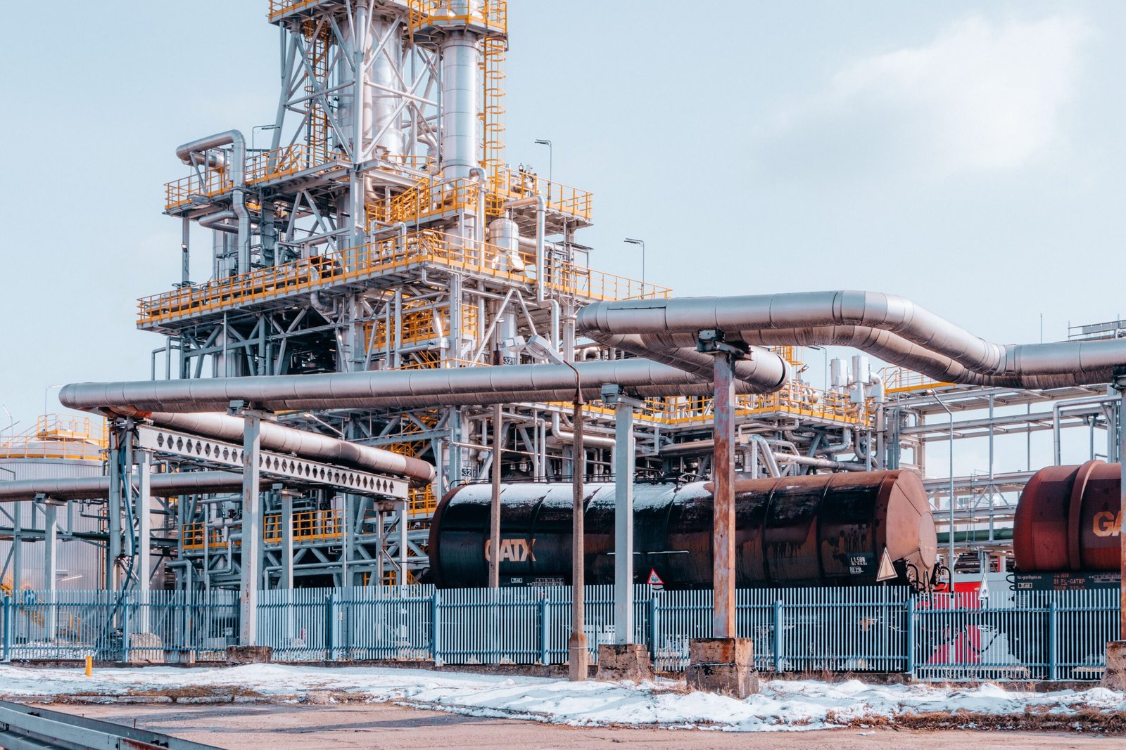 9. Control Valve Selection Checklist for Heat Exchanger Systems
Before requesting a quotation, prepare the following information.
Process and Thermal Requirements
- Application and industry.
- Heat exchanger type and model, if available.
- Heating or cooling objective.
- Required outlet temperature or control variable.
- Hot- and cold-side inlet temperatures.
- Design thermal duty in kW or BTU/h, where available.
- Design, minimum, and maximum flow rates.
- Fluid type and composition.
- Glycol concentration or other relevant fluid properties.
- Minimum and maximum operating temperature.
Hydraulic Requirements
- Upstream and downstream operating pressures.
- Available differential pressure across the valve.
- Expected differential pressure at minimum and maximum flow.
- Pressure drop across the heat exchanger.
- Pump type and operating arrangement.
- Whether the system uses constant or variable flow.
- Required shutoff performance.
- Noise, cavitation, or other hydraulic constraints where relevant.
Valve Requirements
- Valve type: globe, characterized ball, butterfly, three-way, or another suitable design.
- Required Cv or Kv, if already calculated.
- Preferred or required flow characteristic.
- Nominal size and connection standard.
- Body, trim, seat, and seal materials.
- Pressure and temperature ratings.
- Flow direction and installation orientation.
- Required leakage or shutoff specification.
- Minimum and maximum operating range.
Actuator and Control Requirements
- Electric, pneumatic, or other actuator type.
- Power supply or instrument-air conditions.
- Control signal, such as 0–10 V or 4–20 mA, where applicable.
- Open/close or modulating operation.
- Required operating speed.
- Position feedback or positioner requirements.
- Fail-open, fail-closed, or fail-in-place requirement.
- Controller, PLC, or building management system compatibility.
Commercial and Delivery Requirements
- Quantity.
- Existing valve manufacturer and model, if replacing a valve.
- Required documentation and inspection records.
- Customization requirements.
- Delivery deadline.
- Installation constraints.
- Destination country.
- Packaging and export requirements.
- Required spare parts and maintenance support.
Providing this information allows a supplier to evaluate the application more accurately and reduces the risk of selecting an unsuitable valve assembly.
10. Frequently Asked Questions About Control Valves for Heat Exchange Systems
1. What Is the Best Control Valve for a Heat Exchanger?
There is no universally best control valve for every heat exchanger. Globe, characterized ball, butterfly, and three-way valves may all be suitable for different applications. The correct choice depends on flow rate, differential pressure, control accuracy, fluid compatibility, pressure rating, and actuator requirements.
2. How Do I Calculate the Required Cv for a Heat Exchanger Control Valve?
For a preliminary liquid-service calculation, use the required flow rate and the pressure drop available across the valve in the applicable Cv relationship. Confirm the result against manufacturer sizing data and account for fluid properties, operating range, and special conditions such as cavitation or flashing where relevant.
3. What Is the Difference Between Cv and Kv?
Cv and Kv are flow-capacity coefficients used in valve sizing. Cv is commonly used in US practice, while Kv is used in metric practice. They are based on different unit conventions, so calculations must use the appropriate coefficient and corresponding flow and pressure units.
4. Should I Use a Two-Way or Three-Way Control Valve?
Use a two-way valve when the system is designed to regulate flow through a single controlled path. A three-way valve may be appropriate for mixing or diverting flow. The choice depends on the piping arrangement, pump strategy, control objective, and hydraulic requirements.
5. Why Does My Heat Exchanger Control Valve Keep Opening and Closing?
Repeated valve movement can result from oversizing, unsuitable valve authority, incorrect controller tuning, noisy temperature measurements, unstable flow, or insufficient system differential pressure. Check the control loop and hydraulic conditions before changing the actuator or replacing the valve.
6. What Is Valve Authority in a Heat Exchange System?
Valve authority is a measure of the control valve’s pressure drop relative to the pressure drop across the relevant circuit at a defined operating condition. It helps engineers assess how system pressure changes affect the installed valve characteristic and control performance.
7. Is an Electric or Pneumatic Actuator Better for a Heat Exchanger?
Neither is universally better. Electric actuators are common in HVAC and industrial automation, while pneumatic actuators are often used where suitable instrument air is available. Selection depends on control requirements, infrastructure, actuator sizing, maintenance, and the required failure response.
8. What Does Fail-Closed Mean for a Control Valve?
Fail-closed means the valve is designed to move toward the closed position following a specified failure, such as loss of power or instrument air. Whether this function is required depends on the process design and the consequences of continued heating or cooling.
9. Can I Use a Standard Ball Valve to Control Heat Exchanger Temperature?
A standard ball valve should not automatically be used for modulating temperature control. Select a valve designed and rated for the required control duty, with appropriate flow characteristics, actuator compatibility, and operating range.
10. Can a Control Valve Reduce Heat Exchanger Energy Consumption?
A correctly selected and controlled valve can help reduce unnecessary flow and improve part-load operation. Actual energy savings depend on the complete system, including pump operation, pressure drop, heat exchanger performance, control logic, and thermal demand.
11. What Causes Excessive Noise in a Heat Exchanger Control Valve?
Possible causes include excessive differential pressure, high fluid velocity, cavitation, unsuitable valve sizing, or mechanical vibration. The cause should be identified from operating data and manufacturer guidance before changing the valve or system settings.
12. How Do I Know Whether a Control Valve Is Undersized?
A valve may be undersized if it cannot provide the required flow under the specified operating conditions, but other restrictions or insufficient upstream pressure can produce similar symptoms. Verify flow, differential pressure, valve position, heat exchanger condition, and the manufacturer’s sizing data before replacing it.
13. What Materials Should I Choose for a Heating-Water Control Valve?
The correct materials depend on water chemistry, treatment chemicals, temperature, pressure, and the required service life. Common body materials include cast iron, ductile iron, carbon steel, and stainless steel, depending on the application. Confirm compatibility for the body, trim, seat, and seals.
14. Can a Control Valve Be Replaced Without Recalculating the System?
A direct replacement may be possible if the existing valve’s specifications are known and the operating conditions remain unchanged. However, verify the flow coefficient, characteristic, pressure rating, connection, materials, actuator, and control requirements rather than relying on nominal size alone.
15. What Information Should I Send a Supplier for a Control Valve Quotation?
Provide the required flow rate, fluid type, temperature, operating pressure, available differential pressure, control objective, valve size and connection, material requirements, actuator and signal specifications, fail position, quantity, and destination country. Existing datasheets and nameplate photographs are useful for replacement projects.
11. Choosing a Control Valve Supplier for International Projects
A suitable supplier should be able to understand the application, review the available technical data, and coordinate a valve and actuator assembly that matches the system requirements.
What Should Buyers Verify?
Technical selection support: The supplier should request the relevant flow, pressure, temperature, fluid, and control information rather than recommending a valve based on pipe diameter alone.
Product documentation: Review datasheets, pressure and temperature ratings, flow coefficients, material specifications, actuator data, connection dimensions, and relevant inspection records.
Manufacturing coordination: For customized or non-standard requirements, confirm that the proposed manufacturing partner can supply the required configuration and supporting documentation.
Quality control: Agree on the required product identification, inspection scope, and documentation before placing the order.
Control compatibility: Confirm that the actuator and accessories match the site’s electrical, pneumatic, and control-system requirements.
Export coordination: Verify packaging, shipping arrangements, documentation, delivery terms, and destination-specific requirements.
After-sales communication: Establish how technical questions, replacement parts, and product documentation will be handled after delivery.
As an international trading and export company, we work closely with qualified manufacturing partners and engineering teams to support product sourcing, technical coordination, customization, quality control, and international export arrangements.
The final valve selection should be confirmed using the actual process conditions, hydraulic calculations, manufacturer specifications, and applicable project requirements.
12. Request a Quote for Control Valves for Heat Exchange Systems
Need a control valve for a plate heat exchanger, shell-and-tube heat exchanger, heating station, cooling circuit, or industrial heat transfer unit?
The right valve helps maintain stable temperature control, regulate flow, and support reliable system operation. A properly specified actuator and compatible control arrangement are equally important.