A catalog heat exchanger covers maybe 70% of industrial duties. The rest — high pressure, aggressive fluids, tight footprints, heavy fouling — has to be engineered from scratch. That is where projects stall, because the design questions come before the commercial ones.
Here is how custom heat exchanger design actually works when the operating conditions fall outside the standard envelope.
Why standard units fail first
Most failed installations we get called in on share the same root causes:
Tube wall corrosion through in 18–24 months
Fouling that cannot be cleaned without cutting the shell open
Vibration fatigue cracking at tube-to-tubesheet joints
Thermal expansion tearing gaskets or cracking welds
Pressure drop so high the pump cannot make duty
None of these are manufacturing defects. They are design mismatches. A standard unit was selected on the basis of duty, not on the basis of the fluid, the environment, or the maintenance reality.
1. Define the real operating envelope, not the datasheet
The single biggest source of error in non-standard heat exchanger design is an incomplete spec. Normal operation is not the design case.
Include:
Startup, shutdown, and upset conditions — thermal shock from a cold start is often the governing stress case
Turndown — a unit sized for 100% flow may foul or stratify at 30%
Ambient conditions — winter freeze-up, offshore salt spray, desert dust
Cleaning cycles — CIP temperature and chemistry can be more aggressive than the process itself
Design vs operating pressure and temperature — keep them distinct; they are not the same number
Design codes matter here. In the US, ASME BPVC Section VIII Div. 1 with TEMA class R, C, or B. In Europe, PED 2014/68/EU with EN 13445. Offshore and sour service adds NACE MR0175 / ISO 15156. Tell your manufacturer which applies before they start, not after.
2. Fouling and scaling service
Fouling is the most common reason a heat exchanger underperforms. Design responses that work:
Tune velocity. For water on the tube side, 1–2 m/s is the usual sweet spot. Below that, solids settle. Above it, erosion accelerates.
Increase tube pitch and use square layout so the outside of the bundle can be mechanically cleaned.
Specify removable bundles or a floating head if chemical cleaning is not practical.
Use wide-gap plate channels for fibrous or particulate slurries.
Consider a spiral heat exchanger for solids-laden or highly viscous streams — the single-channel geometry is self-scouring and has no dead zones.
One warning: over-specifying fouling resistance is a common mistake. Adding 30% extra surface often drops the velocity below the self-cleaning threshold, and the unit fouls faster than the correctly sized one. Fouling allowance should be a calculated decision, not a default multiplier.
3. Corrosive fluids and material selection
Material selection drives both cost and service life. Practical guidance:
Seawater: titanium, super duplex stainless, or CuNi 90/10. Watch velocity limits — CuNi erodes above roughly 2.5 m/s.
Chlorides: 304 and 316 are vulnerable to stress corrosion cracking above about 60 °C. Move to duplex, 6Mo, or titanium.
Strong acids: Hastelloy C276, Alloy 20, PTFE-lined steel, or impervious graphite depending on concentration and temperature.
Caustic: nickel or nickel alloys.
Sour service: materials qualified to NACE MR0175 / ISO 15156.
Do not forget gaskets and dissimilar metal contacts. A titanium tube bundle with a carbon steel channel and the wrong gasket will fail at the joint long before the tubes do.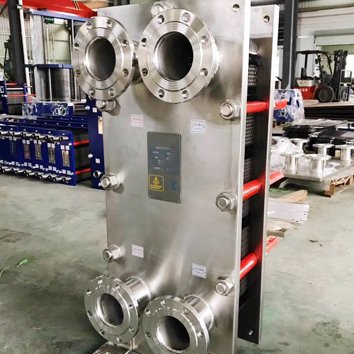
4. High pressure and high temperature
Above roughly 40 bar, geometry changes:
Small-diameter tubes with thick walls in a shell-and-tube design reduce hoop stress and tubesheet thickness
Welded plate heat exchangers eliminate gaskets and handle higher pressure in a smaller frame
Printed circuit heat exchangers (PCHE) handle extreme pressure and temperature in a fraction of the volume — common in hydrogen, supercritical CO₂, and offshore service
Bayonet and double-pipe designs remain the practical answer for very high pressure with clean fluids
Above 400 °C for carbon steel, creep becomes a design concern, not just yield strength. Thermal stress analysis — often FEA — is not optional at that point.
5. Space and weight constraints
Offshore platforms, skid-mounted packages, and plant retrofits rarely have room for a conventional shell-and-tube unit. Compact alternatives:
Brazed plate (limited to clean fluids, moderate pressure)
Welded plate (gasket-free, higher pressure)
Plate-fin for gas-to-gas duty
PCHE for the most demanding envelope
A compact unit can cut footprint by 70–90% compared to shell-and-tube. The trade-off is usually cleanability — weigh that against the cost of downtime.
6. Phase change and two-phase flow
Condensers, reboilers, and evaporators behave differently from single-phase units:
Maldistribution in plate units causes uneven boiling and premature dryout
Thermosiphon reboilers need careful static head calculation to stay stable
Kettle reboilers handle wide boiling ranges better than forced-circulation alternatives
Condensers with non-condensables need venting provisions designed in, not added later
Give your manufacturer the full vapor-liquid equilibrium data, not just inlet and outlet temperatures.
7. Vibration and thermal expansion
Tube vibration destroys more heat exchangers than corrosion in high-flow gas service. Mitigation:
Vibration analysis per TEMA or HTRI methods
Tube supports at calculated spacing
“No tubes in window” layout to eliminate the most vulnerable tubes
U-bend, floating head, or expansion joint to absorb differential thermal growth
If your unit has failed repeatedly at tube-to-tubesheet joints, this is almost always the answer.
8. Retrofits and obsolete replacements
A large share of custom work is replacing a unit that has no drawings, no nameplate, or a manufacturer that no longer exists.
The approach:
Reverse-engineer from the physical unit and piping
Match nozzle orientation, footprint, and connection sizes to avoid re-piping
Match or exceed the original duty with modern materials
Upgrade to a better alloy or geometry while you are already paying for the change
This is often cheaper than a new installation, because the civil, piping, and structural work is already done.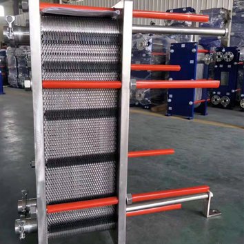
What to send for a custom quote
The more complete this list, the faster and more accurate the design:
Heat duty or required outlet temperature
Flow rate, both sides
Inlet and outlet temperatures, both sides
Fluid composition and concentration
Design pressure and temperature (separate from operating)
Fouling allowance, if specified
Allowable pressure drop, both sides
Required materials of construction
Applicable codes and stamps (ASME U, PED, NACE, ATEX)
Available utilities and their conditions
Space, weight, and connection limits
Cleaning method and frequency
Missing items 5 through 8 cause most of the back-and-forth in custom heat exchanger projects.
FAQ
How long does a custom heat exchanger take to design and build?
Thermal and mechanical design typically runs 1–3 weeks. Fabrication depends on materials and code requirements — 8 to 16 weeks is normal for alloy shell-and-tube units, longer for exotic alloys or stamped pressure vessels.
Is a custom unit much more expensive than a standard one?
The engineering premium is usually 5–15% of unit cost. That is almost always recovered within the first maintenance cycle, because the unit is sized for the actual fluid and cleaning method rather than a catalog assumption.
Can you replace an obsolete heat exchanger with no drawings?
Yes. Send photos, dimensions, nozzle locations, and nameplate data if available. Field measurement is enough in most cases.
Should I oversize for future capacity?
Only if the turndown case still works. An oversized unit running at low velocity fouls faster and controls poorly. Design for the range, not the maximum.