Designing an energy-efficient data center cooling system is not simply a matter of selecting high-efficiency air conditioners or chillers. The real challenge is to remove heat from IT equipment reliably while minimizing the energy used by fans, pumps, compressors, and heat-rejection equipment.
A cooling system that is oversized, poorly controlled, or mismatched to rack density can consume unnecessary energy even when its equipment has high rated efficiency. Conversely, a well-designed system coordinates IT load, airflow, cooling distribution, heat rejection, redundancy, and environmental conditions as one integrated infrastructure.
For data center owners, facility managers, and MEP engineers, the most effective approach is to establish the actual cooling requirements first, select an appropriate cooling architecture, and optimize the complete system under realistic operating conditions.
1. Start with IT Load and Cooling Requirements
The first step in designing an energy-efficient data center cooling system is to understand how much heat must be removed, where it is generated, and how the load is expected to change.
Calculate the actual cooling load
Most electrical power consumed by IT equipment is ultimately converted into heat inside the data center. Therefore, IT electrical load is a useful starting point for estimating the cooling requirement.
However, the total facility cooling load may also include:
UPS and power distribution losses located inside the conditioned space
Lighting and occupancy loads
Heat transfer through walls, roofs, floors, and windows
Outdoor air and ventilation loads, where applicable
Heat generated by other equipment inside the data hall
A simplified calculation is:
Total cooling load = IT heat load + electrical losses + lighting and occupancy loads + building and ventilation heat gains
For example, consider a data hall with:
IT load: 500 kW
Electrical equipment losses: 20 kW
Lighting and occupancy: 5 kW
Building and ventilation heat gains: 15 kW
The estimated cooling load is:
500 + 20 + 5 + 15 = 540 kW
This is an illustrative load estimate, not a final equipment selection. The design must also account for operating conditions, sensible and latent loads, redundancy, future expansion, and the performance of the complete cooling chain.
Analyze rack-level heat density
An average room-level load does not reveal how heat is distributed.
For example, a data hall may have a moderate average rack density but contain several high-density GPU racks. A room-level cooling system sized around the average may leave these racks with insufficient airflow or cooling capacity.
Before selecting equipment, collect:
Total and projected IT power
Power consumption by rack
Maximum expected rack density
Rack layout and equipment dimensions
Server inlet temperature requirements
Planned deployment and expansion phases
Whether workloads create significant variations in heat load
For high-density computing, design around the actual rack-level load profile rather than relying only on total room capacity.
2. Optimize Airflow Before Increasing Cooling Capacity
Poor airflow management is a common source of unnecessary cooling energy consumption. Cooling equipment may operate at high fan speeds and low supply-air temperatures simply because cold air is not reaching server inlets efficiently.
The objective is to deliver the required volume of supply air to IT equipment and return hot exhaust air to the cooling system without allowing the two air streams to mix unnecessarily.
Use hot aisle and cold aisle arrangements
In a conventional hot aisle/cold aisle layout, server racks are arranged so that their cold-air intakes face one another, forming cold aisles. Server exhausts face one another, forming hot aisles.
This arrangement creates a more predictable airflow path and provides a foundation for containment.
Consider cold aisle or hot aisle containment
Containment physically separates supply air from hot exhaust air.
| Approach | Main function | Design consideration |
|---|---|---|
| Cold aisle containment | Encloses the cold aisle to protect supply air | Requires a suitable return-air path and pressure management |
| Hot aisle containment | Encloses the hot aisle to capture hot exhaust | Requires a compatible ceiling or return-air arrangement |
| No containment | Relies on room layout and airflow management | May be suitable for some low-density or existing facilities, but is more exposed to air mixing |
Containment can reduce bypass airflow and hot-air recirculation. It may also allow cooling units to operate with higher supply-air temperatures or lower fan speeds, provided rack inlet conditions remain within equipment requirements.
Containment alone does not guarantee efficiency. Poorly positioned floor tiles, cable openings, missing blanking panels, blocked server intakes, and inadequate return-air paths can still undermine performance.
Match airflow to IT demand
Excessive airflow increases fan energy and may create pressure or distribution problems. Insufficient airflow can cause high rack inlet temperatures and localized hot spots.
Practical measures include:
Use blanking panels in unused rack spaces.
Seal cable openings and other unintended air leakage paths.
Keep server intakes and exhausts unobstructed.
Review perforated tile placement and airflow distribution.
Use variable-speed fans where appropriate.
Adjust fan operation according to actual IT load and rack inlet conditions.
Check airflow at the most demanding racks, not just at room level.
A useful principle is to provide enough airflow for the hottest or most demanding rack under the design operating condition, without unnecessarily over-supplying the entire room.
3. Select the Right Cooling Architecture
The most energy-efficient cooling architecture depends on rack density, climate, available utilities, building configuration, reliability requirements, and future expansion plans. No single technology is optimal for every data center.
Compare common data center cooling systems
| Cooling technology | Typical application | Main advantages | Important considerations |
|---|---|---|---|
| CRAC | Smaller or distributed data rooms; DX-based cooling | Self-contained refrigeration-based configuration | Compressor energy, refrigerant system design, and maintenance |
| CRAH | Data halls using chilled-water infrastructure | Integrates with central chilled-water systems | Chiller and pump efficiency, water temperature, and control strategy |
| In-row cooling | Medium- to high-density rack rows | Places cooling closer to the heat source | Row layout, piping or refrigerant routing, and redundancy |
| Rear door heat exchanger | High-density racks requiring localized heat removal | Captures heat at the rack exhaust | Water-loop design, pressure drop, and rack compatibility |
| Direct-to-chip liquid cooling | GPU and high-performance computing racks | Transfers heat directly from selected components into liquid | CDU configuration, coolant quality, flow, pressure, and facility-water interface |
| Immersion cooling | Specialized high-density computing environments | Removes heat through dielectric fluid surrounding IT equipment | IT hardware compatibility, fluid management, tank design, and service procedures |
When to use CRAC and CRAH systems
CRAC systems typically use direct expansion refrigeration to cool the air. CRAH systems use chilled water supplied by an external chiller plant.
A CRAC-based design may be appropriate where a chilled-water plant is unavailable or where distributed DX cooling fits the project. A CRAH-based design may be attractive where a central chilled-water system can serve the data hall efficiently.
The comparison should not stop at the rated efficiency of the indoor unit. Evaluate the complete system, including compressors, chillers, pumps, condenser equipment, fans, controls, and part-load performance.
When to consider in-row and rear-door cooling
As rack density increases, room-based cooling may become less effective at delivering sufficient airflow to every server.
In-row cooling places cooling equipment between or near server racks, shortening the air path and helping address localized heat loads.
Rear door heat exchangers remove heat from server exhaust as it leaves the rack. Depending on the configuration, they can reduce the amount of heat released into the room and support higher rack densities.
These systems should be evaluated against rack power, airflow, water availability, maintenance access, and the required level of redundancy.
When liquid cooling becomes appropriate
Direct-to-chip liquid cooling is increasingly relevant for GPU and high-performance computing environments where a substantial proportion of heat is concentrated in processors and accelerators.
A typical system may include:
Cold plates installed on selected IT components
Coolant distribution manifolds
A Coolant Distribution Unit (CDU)
A technology cooling system loop
A facility water system or heat-rejection interface
The CDU separates and manages the IT-side coolant circuit and the facility-side heat-removal circuit according to the selected design.
Liquid cooling does not necessarily eliminate the need for air cooling. Memory, power supplies, storage devices, networking equipment, and other components may continue to release heat into the room. A hybrid design may therefore be required.
Immersion cooling is a different architecture in which compatible IT equipment is immersed in dielectric fluid. It requires specific hardware, fluid, tank, and maintenance considerations and should not be treated as interchangeable with direct-to-chip cooling.
4. Reduce Compressor Energy with Economizers and Efficient Heat Rejection
Cooling equipment does not always need to rely on mechanical refrigeration. Depending on the climate and system design, outdoor conditions can be used to reject heat with less compressor operation.
Evaluate airside and waterside economizers
An airside economizer uses suitable outdoor air to provide some or all of the cooling required by the data hall. It requires careful consideration of outdoor air quality, filtration, humidity, contamination, and environmental limits.
A waterside economizer uses favorable outdoor conditions to cool a water or fluid loop through equipment such as a cooling tower or dry cooler, reducing or avoiding chiller compressor operation when conditions permit.
| Approach | How it works | Key considerations |
|---|---|---|
| Airside economizer | Uses filtered outdoor air for cooling | Air quality, humidity, filtration, corrosion, and building design |
| Waterside economizer | Uses outdoor conditions to cool a water loop | Ambient conditions, heat exchanger approach, water use, and system temperatures |
| Dry cooler | Rejects heat to outdoor air through a closed fluid circuit | Outdoor dry-bulb temperature, coil capacity, fan energy, and fluid temperature |
| Cooling tower | Uses evaporative heat rejection | Water availability, water treatment, blowdown, and maintenance |
Economizer hours depend on local climate, operating temperatures, humidity limits, and the selected system configuration. A solution that performs well in a cool climate may provide limited benefit in a hot and humid region.
Select chillers and heat-rejection equipment as one system
A chiller’s rated efficiency does not represent the energy consumption of the entire cooling plant.
The design should consider:
Chiller efficiency at expected operating conditions
Part-load performance
Chilled-water supply and return temperatures
Condenser-water temperatures, where applicable
Pump head and flow requirements
Cooling tower or dry cooler fan power
Heat exchanger pressure drop
Equipment staging and redundancy
Seasonal changes in outdoor conditions
A higher chilled-water supply temperature may improve chiller efficiency and increase the opportunity for waterside economization, but only if the downstream cooling equipment can still meet IT inlet requirements.
Do not select a higher water temperature simply to improve a chiller’s efficiency rating. Validate the complete heat-transfer path.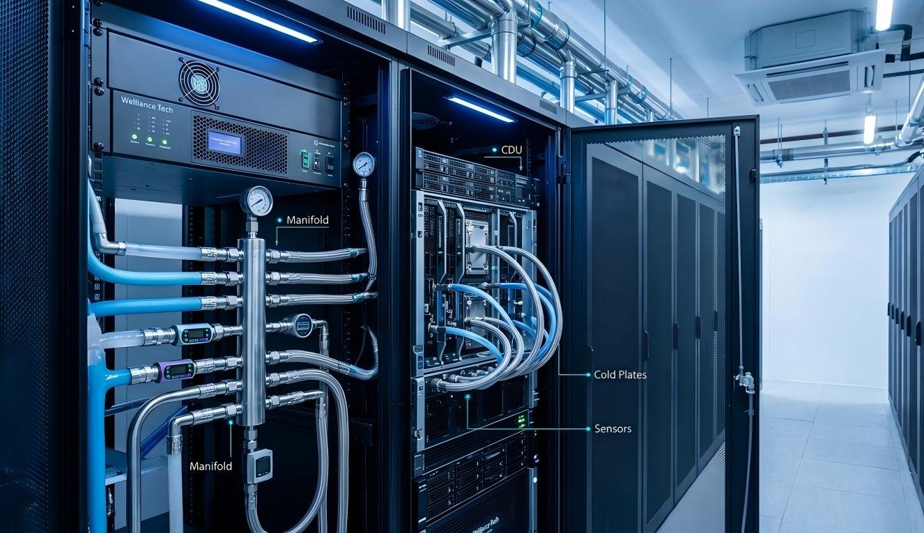
5. Design Controls, Redundancy, and Scalability Together
An energy-efficient cooling system must respond to changing IT loads without compromising reliability.
Use variable-speed equipment and coordinated controls
Cooling demand changes as servers are added, removed, or operated at different utilization levels. Fixed-speed fans and pumps may consume unnecessary energy when demand is low.
Where technically suitable, consider:
Variable-frequency drives for fans and pumps
Supply-air temperature reset
Chilled-water temperature reset
Differential-pressure control
Cooling-unit staging
Economizer enable and disable sequences
Load-based control of CDUs and secondary pumps
Coordinated alarms and operating limits
Controls should respond to actual operating conditions rather than relying only on fixed room setpoints.
For example, a fan-speed control strategy can use rack inlet temperatures and airflow requirements to maintain acceptable conditions while avoiding unnecessary fan operation. However, control sequences must be tested under different load conditions to prevent unstable operation or inadequate cooling at critical racks.
Plan redundancy without unnecessary energy waste
Data centers may require N, N+1, or 2N cooling configurations depending on availability targets and project requirements.
N: Capacity sufficient to meet the design load, without additional redundant capacity.
N+1: One additional capacity unit beyond the required number.
2N: Two independent systems, each designed to support the required load.
Redundancy affects equipment quantity, plant arrangement, operating sequences, and part-load efficiency. A design with redundant equipment must also define how units operate during normal conditions, maintenance, equipment failure, and peak demand.
Avoid simply installing additional equipment without evaluating staging and control logic. Poor sequencing can cause multiple units to operate inefficiently at low loads.
Design for future expansion
A cooling system designed only for the initial IT load may become inefficient or difficult to expand as rack density increases.
Consider:
Modular cooling capacity
Space for additional cooling units
Electrical capacity for future equipment
Chilled-water or coolant distribution capacity
Pipe routing and connection points
CDU placement and service access
Structural loading for racks and cooling equipment
Isolation and maintenance arrangements
For AI data centers, the future rack density and liquid-cooling strategy should be considered early. Retrofitting liquid distribution, heat rejection, and electrical infrastructure after the data hall is operational can be more disruptive than planning for expansion during initial design.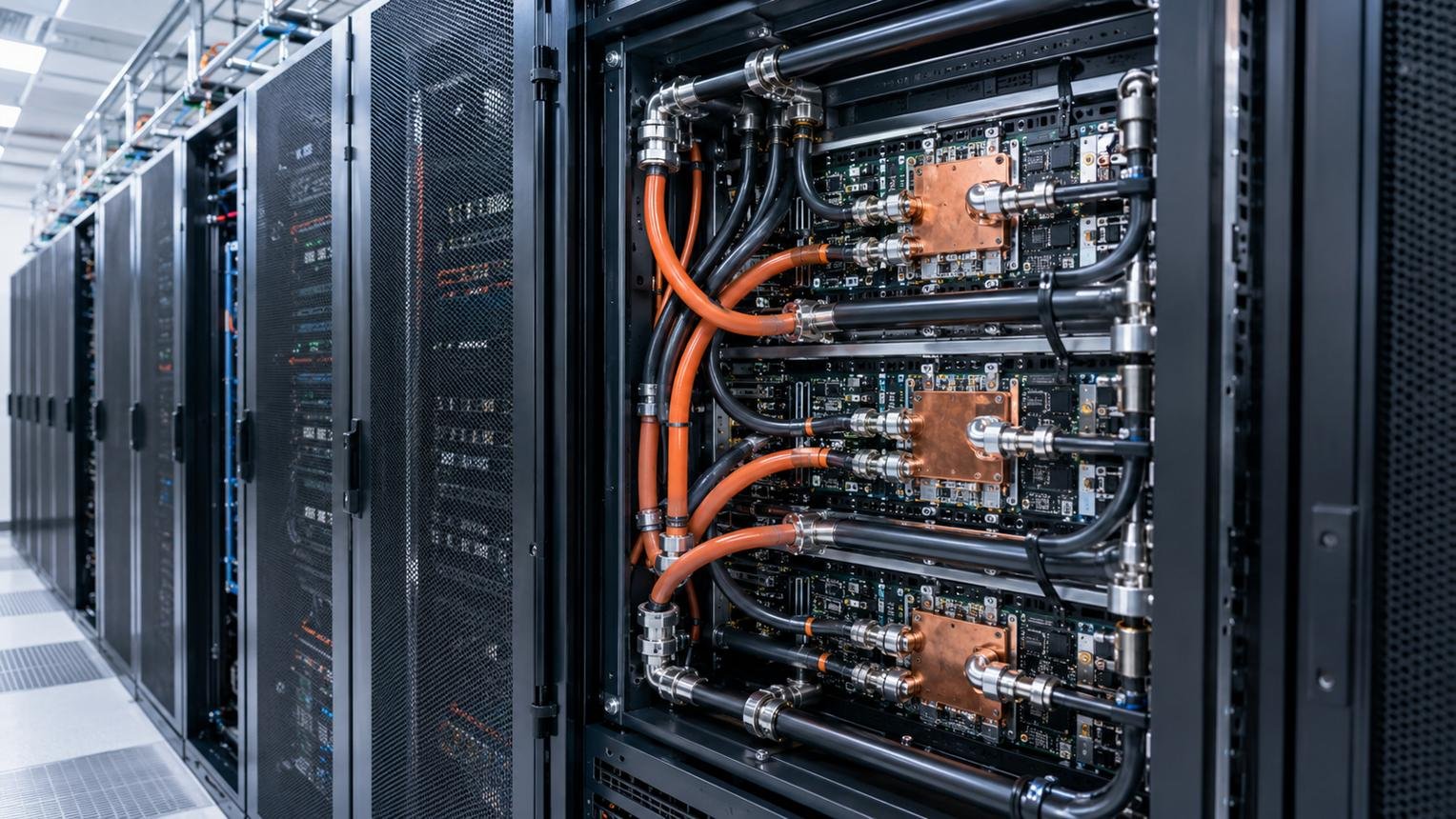
6. Measure Cooling Efficiency and Validate Real Operating Performance
An energy-efficient design must be measurable. Equipment selection calculations should be followed by commissioning, monitoring, and continuous optimization.
Understand PUE and its limitations
Power Usage Effectiveness (PUE) is a commonly used data center energy metric:
PUE = Total facility energy / IT equipment energy
A lower PUE indicates that less additional facility energy is used relative to IT energy. Cooling is one important contributor to this additional energy, but PUE also includes power distribution, lighting, and other facility loads.
PUE alone cannot identify whether a particular cooling system is efficient. It can also be affected by IT load, weather, and measurement boundaries.
For a more useful evaluation, monitor cooling-related energy separately, including:
Chiller and compressor electricity
CRAH and CRAC fan energy
Pump energy
Cooling tower and dry cooler fan energy
Humidification and dehumidification energy, where applicable
Economizer operating hours
Cooling energy under different IT load conditions
Where water consumption is important, also consider Water Usage Effectiveness (WUE). Where waste heat is reused, energy reuse metrics may provide additional insight.
Monitor the right operating points
Room temperature alone is not enough to verify cooling performance.
A practical monitoring arrangement should include:
Server rack inlet temperatures
Rack-level temperature distribution
Supply and return air temperatures
Chilled-water or coolant supply and return temperatures
Water or coolant flow rates
Pump and fan speeds
Differential pressure
Cooling-unit operating status
Energy consumption by major equipment
For liquid-cooled systems, monitor the relevant coolant conditions, flow, pressure, and alarms according to the equipment and system design.
Commission the complete cooling system
Commissioning should verify that the cooling system performs as intended under normal and abnormal operating conditions.
A practical commissioning process should include:
Verify equipment installation and connections.
Check airflow, water flow, pressure, and temperature measurements.
Confirm control sequences and operating setpoints.
Test equipment staging and redundancy.
Verify alarms, interlocks, and failure responses.
Confirm rack inlet conditions under representative IT loads.
Record baseline energy and operating data.
After handover, compare actual performance with the design assumptions. Recommissioning and control adjustments may be necessary as IT loads and operating patterns change.
7. Common Mistakes to Avoid in Energy-Efficient Cooling Design
| Design mistake | Why it causes problems | Better approach |
|---|---|---|
| Selecting equipment based only on nominal efficiency | Rated performance may not reflect actual operating conditions | Compare complete-system performance at project conditions |
| Oversizing cooling equipment | Can lead to inefficient part-load operation and higher capital cost | Use a realistic load profile and staged capacity |
| Ignoring rack-level heat density | Average room conditions can hide local hot spots | Assess individual rack power and inlet temperatures |
| Overcooling the entire data hall | Increases compressor and fan energy unnecessarily | Optimize setpoints within equipment environmental requirements |
| Poor containment and airflow management | Causes bypass air and hot-air recirculation | Validate supply and return airflow paths |
| Choosing economizers without climate analysis | Outdoor conditions may limit operating hours or introduce air-quality risks | Evaluate climate, humidity, filtration, and water availability |
| Treating liquid cooling as a complete replacement for air cooling | Some IT components may remain air-cooled | Assess residual room heat and hybrid cooling requirements |
| Ignoring controls and commissioning | Efficient equipment may operate inefficiently as a system | Validate sequences, sensors, alarms, and part-load behavior |
Conclusion
An energy-efficient data center cooling system is the result of coordinated engineering decisions, not one high-efficiency product.
Start with accurate IT and rack-level load analysis. Improve airflow before adding cooling capacity. Select CRAC, CRAH, in-row, rear-door, or liquid cooling according to actual heat density and project conditions. Evaluate economizers and heat-rejection equipment against the local climate. Finally, integrate controls, redundancy, monitoring, and commissioning so that the system remains efficient as IT demand changes.
For AI and high-density data centers, early coordination between IT equipment, liquid-cooling infrastructure, facility water systems, and heat rejection is particularly important.
Planning a new data center or upgrading an existing cooling system? Contact our team to discuss your IT load, rack density, operating environment, and cooling requirements. We can help identify the equipment and system configuration that should be evaluated for your project.