Heat transfer station selection should be based on heat load, primary and secondary temperatures, flow rate, pressure, pressure drop, control requirements, water quality, and future load conditions. The heat exchanger is the core component, but a reliable station also requires correctly sized pumps, control valves, sensors, piping, safety devices, and controls.
Selecting only by nominal heating capacity or heat exchanger size can lead to excessive pressure drop, unstable temperature control, insufficient peak capacity, high energy consumption, or difficult maintenance.
This guide explains how to select and size a heat transfer station for district heating, building HVAC, industrial heating, process applications, and other hydronic systems.
Table of Contents
- Quick Answer: What Is Heat Transfer Station Selection?
- What Parameters Are Needed for Heat Transfer Station Selection?
- How Do You Calculate Heat Transfer Station Capacity?
- How Do You Select the Heat Exchanger for a Heat Transfer Station?
- How Do You Select Pumps, Valves, and Control Components?
- How Do Pressure Drop, Fouling, and Temperature Approach Affect Selection?
- How Should Materials, Certification, and Maintenance Be Considered?
- How to Select a Heat Transfer Station Step by Step
- Common Mistakes in Heat Transfer Station Selection
- Heat Transfer Station Selection Checklist
- FAQ
- Key Takeaways
Quick Answer: What Is Heat Transfer Station Selection?
Heat transfer station selection means choosing and sizing the heat exchanger, pumps, valves, controls, piping, safety components, and supporting equipment to deliver the required heating or cooling duty under actual operating conditions.
A typical heating station separates a primary heat source circuit from a secondary consumer circuit.
For example:
Primary heating network
        ↓
Isolation valve
        ↓
Control valve
        ↓
Heat exchanger
        ↓
Secondary heating system
        ↓
Building / Process Load
A complete selection should answer five basic questions:
- How much heat must be transferred?
- At what temperatures and flow rates?
- At what operating and design pressures?
- What pressure drop is acceptable?
- What control, material, certification, and maintenance requirements apply?
For many projects, the basic thermal calculation is:
[
Q = \dot{m} C_p \Delta T
]
Where:
- Q = heat duty
- ṁ = mass flow rate
- Cp = specific heat
- ΔT = temperature difference
The final equipment selection must then be checked for thermal performance, hydraulic performance, mechanical strength, control stability, and lifecycle cost.
What Parameters Are Needed for Heat Transfer Station Selection?
The most important selection parameters are heat load, fluid properties, temperatures, flow rates, pressure, allowable pressure drop, and operating conditions.
Primary-side data
For the heat source circuit, collect:
- Fluid type
- Flow rate
- Inlet temperature
- Outlet temperature
- Operating pressure
- Design pressure
- Operating temperature
- Design temperature
- Fluid chemistry
- Water quality
- Available pressure differential
Secondary-side data
For the building or process circuit, collect:
- Fluid type
- Flow rate
- Inlet temperature
- Required outlet temperature
- Operating pressure
- Design pressure
- Design temperature
- Required pressure drop
- Load profile
Project requirements
Also define:
- Peak heating load
- Normal heating load
- Minimum load
- Future expansion
- Redundancy requirement
- Installation space
- Connection sizes
- Control philosophy
- Electrical requirements
- Certification requirements
- Maintenance access
- Required delivery date
Why is the load profile important?
A station designed only around peak load can be unnecessarily large and inefficient during most of the year.
For a building, the actual demand may vary substantially:
Peak winter load       ██████████
Normal winter load     ███████
Spring/autumn load     ████
Summer load            █
The control system must therefore operate effectively under both high and low load conditions.
Basic selection data table
| Parameter | Example | Why it matters |
|---|---|---|
| Heat load | 2 MW | Determines thermal capacity |
| Primary inlet | 120°C | Determines heat-transfer conditions |
| Primary outlet | 80°C | Determines primary flow |
| Secondary inlet | 60°C | Determines temperature driving force |
| Secondary outlet | 90°C | Defines useful heat delivery |
| Primary pressure | 1.6 MPa | Determines pressure rating |
| Secondary pressure | 1.0 MPa | Determines secondary design |
| Allowable pressure drop | 80 kPa | Affects exchanger and pump sizing |
| Fluid | Water | Determines thermal properties |
| Future capacity | +15% | Affects design margin |
Actual project values must be calculated from the specific system rather than copied from a generic example.
How Do You Calculate Heat Transfer Station Capacity?
Heat transfer station capacity should be calculated from the required heat load rather than selected from a nominal equipment rating.
Basic heating calculation
For water or another sensible-heating fluid:
[
Q = \dot{m} C_p \Delta T
]
For water, a commonly used engineering approximation is:
[
Q(kW) \approx 1.163 \times \dot{V}(m^3/h) \times \Delta T(°C)
]
Therefore:
[
\dot{V} \approx \frac{Q}{1.163\Delta T}
]
For example, for a 1,000 kW heating load and a 20°C secondary-side temperature difference:
[
\dot{V} \approx \frac{1000}{1.163 \times 20}
]
[
\dot{V} \approx 43.0\ m^3/h
]
This is a simplified calculation. Actual sizing should use the appropriate fluid density and specific heat at the operating temperature.
Heat exchanger area
After determining the heat duty, the heat exchanger can be evaluated using:
[
Q = U A \Delta T_{lm}
]
Therefore:
[
A = \frac{Q}{U\Delta T_{lm}}
]
Where:
- A = heat-transfer area
- U = overall heat-transfer coefficient
- ΔTlm = log mean temperature difference
The actual value of U depends on:
- Fluid properties
- Flow velocity
- Heat exchanger geometry
- Material
- Fouling
- Flow arrangement
- Surface condition
Why should you avoid excessive design margin?
Some margin is often appropriate, but excessive oversizing can cause:
- Higher capital cost
- Poor low-load control
- Oversized valves
- Low flow velocity
- Potential fouling problems
- Unnecessary installation space
- Reduced control stability
The correct margin should reflect actual load uncertainty and future expansion requirements.
How Do You Select the Heat Exchanger for a Heat Transfer Station?
The heat exchanger should be selected by matching thermal duty, pressure drop, pressure and temperature rating, fluid compatibility, fouling conditions, maintenance requirements, and available space.
Gasketed plate heat exchanger
A gasketed plate heat exchanger is commonly selected for hydronic heating and cooling because it provides high heat-transfer efficiency in a compact package.
Typical advantages:
- High heat-transfer coefficient
- Compact footprint
- Removable plates
- Relatively easy cleaning
- Flexible capacity adjustment
- Replaceable gaskets
Important selection factors include:
- Plate material
- Plate thickness
- Plate pattern
- Number of plates
- Gasket material
- Connection size
- Design pressure
- Design temperature
Brazed plate heat exchanger
Brazed plate heat exchangers are compact and often used where a small footprint is important.
They can be suitable for:
- HVAC
- Refrigeration
- Domestic hot-water applications where appropriate
- Small process systems
However, internal access is more limited than with a gasketed plate heat exchanger.
Welded plate heat exchanger
Welded construction can be useful where gasket limitations make a gasketed design unsuitable.
Applications may include:
- Higher-temperature services
- Certain aggressive fluids
- Industrial process heating
- Refrigeration systems
Shell-and-tube heat exchanger
Shell-and-tube heat exchangers are widely used for industrial and process applications.
Important selection parameters include:
- Shell diameter
- Tube diameter
- Tube length
- Number of tubes
- Tube material
- Tube-sheet material
- Baffle arrangement
- Number of passes
- Design pressure
- Design temperature
Heat exchanger selection comparison
| Factor | Gasketed plate | Brazed plate | Welded plate | Shell-and-tube |
|---|---|---|---|---|
| Compactness | High | Very high | High | Medium |
| Internal access | Good | Limited | Limited/application dependent | Good, depending on design |
| Gasket replacement | Yes | No conventional gasket | Usually minimized | Depends on design |
| Fouling tolerance | Application dependent | Application dependent | Application dependent | Often good with suitable tube layout |
| High-temperature suitability | Gasket dependent | Brazing/material dependent | Often favorable | Often favorable |
| Maintenance | Relatively easy | More limited | Application dependent | Established methods |
| Typical use | HVAC, district heating | Compact HVAC/refrigeration | Process applications | Industrial/process |
There is no universal “best” heat exchanger. The correct choice depends on the complete process.
How Do You Select Pumps, Valves, and Control Components?
The supporting equipment should be sized around the required flow, pressure differential, control range, and system operating conditions.
Pump selection
Pump flow should satisfy the required circulation:
[
\dot{V}{pump} \geq \dot{V}{required}
]
Pump head must account for:
- Heat exchanger pressure drop
- Pipe friction
- Valves
- Filters/strainers
- Elevation where applicable
- Other system components
A simplified relationship is:
[
H \approx \frac{\Delta P}{\rho g}
]
Where:
- H = pump head
- ΔP = pressure difference
- ρ = fluid density
- g = gravitational acceleration
Fixed-speed vs. variable-speed pumps
| Pump approach | Advantages | Limitations |
|---|---|---|
| Fixed speed | Simple control | Less efficient at variable load |
| Variable speed | Better part-load efficiency | Higher control complexity |
| Duty/standby | Higher availability | Higher initial cost |
| Multiple smaller pumps | Flexible staging | More components |
For systems with substantial load variation, variable-speed pumping can reduce unnecessary energy consumption.
Control valve selection
A control valve should be selected according to:
- Design flow
- Differential pressure
- Valve authority
- Required turndown
- Fluid temperature
- Fluid pressure
- Actuator type
- Fail-safe requirement
An oversized valve may operate close to its closed position and become difficult to control accurately.
Sensors
At minimum, temperature measurement is commonly required on the relevant inlet and outlet circuits.
Depending on the application, also consider:
- Pressure sensors
- Differential-pressure sensors
- Flow meters
- Energy meters
- Water-quality monitoring
How Do Pressure Drop, Fouling, and Temperature Approach Affect Selection?
Pressure drop, fouling, and temperature approach directly influence heat exchanger size, energy consumption, reliability, and maintenance cost.
Pressure drop
Pressure drop is the pressure lost as fluid passes through the heat exchanger.
Higher flow velocity generally improves heat transfer but also increases pressure drop.
This creates a design trade-off:
Higher velocity → better heat transfer → potentially higher pressure drop
The selected heat exchanger should remain within the pressure-drop limit specified by the system.
Temperature approach
Temperature approach is the temperature difference between the relevant hot and cold streams at the closest point in the heat exchanger.
A smaller approach generally requires:
- More heat-transfer area
- More precise thermal design
- Potentially higher equipment cost
- Careful control of flow rates
Fouling
Fouling adds thermal resistance and can reduce performance over time.
A simplified overall thermal resistance relationship is:
[
\frac{1}{U} \approx \frac{1}{h_1}+R_{f1}+R_{wall}+R_{f2}+\frac{1}{h_2}
]
Where Rf1 and Rf2 represent fouling resistance.
Fouling can also increase pressure drop when deposits restrict flow passages.
How should fouling affect station selection?
For high-fouling applications, consider:
- Larger channels
- Appropriate flow velocity
- Filtration
- Easy cleaning
- Removable plate construction
- Tube-cleaning access
- Suitable fouling allowance
Hydraulic and thermal comparison
| Design choice | Capital cost | Energy effect | Maintenance effect |
|---|---|---|---|
| Smaller exchanger | Lower | May increase pump demand | Potentially more sensitive to fouling |
| Larger exchanger | Higher | May reduce pressure drop | More thermal margin |
| Narrow plate channels | Compact | Potentially higher pressure drop | Can be sensitive to solids |
| Wider channels | Potentially larger | Lower velocity for same flow | Can improve tolerance for some fluids |
| Very small approach | Higher | Can improve heat recovery | More sensitive to design accuracy |
| Large approach | Lower | May reduce heat recovery | Simpler thermal design |
How Should Materials, Certification, and Maintenance Be Considered?
Materials and compliance requirements should be established before equipment selection because they can change the heat exchanger design, price, lead time, and maintenance strategy.
Material selection
Common materials include:
- Stainless steel
- Carbon steel
- Copper alloys
- Titanium
- Duplex stainless steel
- Nickel alloys
Selection should consider:
- Water chemistry
- Chloride concentration
- pH
- Temperature
- Pressure
- Corrosion risk
- Cleaning chemicals
- Erosion
- Service life
For example, “water” alone is not enough information for material selection.
Gasket selection
For gasketed plate heat exchangers, gasket compatibility should be checked against:
- Temperature
- Fluid
- Chemical cleaning agents
- Pressure
- Operating cycles
A gasket material that performs well in one heating system may not be appropriate for another.
Certification
Depending on the destination and application, requirements may include:
- Pressure-equipment conformity
- Applicable design code
- Material certificates
- Pressure testing
- NDT
- Third-party inspection
- Project-specific QA documentation
- Marine classification where applicable
Certification should be confirmed before manufacturing.
Maintenance strategy
A station should provide sufficient access for:
- Heat exchanger cleaning
- Gasket replacement
- Pump service
- Valve maintenance
- Strainer cleaning
- Sensor replacement
- Drainage and venting
Maintenance access is part of equipment selection, not an afterthought.
How to Select a Heat Transfer Station Step by Step
A practical heat transfer station selection process starts with the load and system conditions, then progressively defines the heat exchanger, pumps, controls, materials, and documentation.
Step 1: Determine the design heat load
Define:
- Peak load
- Normal load
- Minimum load
- Future expansion
Avoid selecting equipment from floor area alone unless the load calculation supports it.
Step 2: Determine primary and secondary conditions
Record:
- Flow rate
- Inlet temperature
- Outlet temperature
- Operating pressure
- Design pressure
- Design temperature
Step 3: Calculate required flow
Use:
[
\dot{m}=\frac{Q}{C_p\Delta T}
]
Then convert mass flow to volumetric flow using the actual fluid density.
Step 4: Determine allowable pressure drop
Establish the maximum pressure drop available for:
- Heat exchanger
- Control valve
- Strainer
- Piping
- Other components
Do not allocate the entire available pressure differential to the heat exchanger.
Step 5: Calculate heat-transfer area
Use:
[
A=\frac{Q}{U\Delta T_{lm}}
]
The supplier should perform detailed thermal selection using actual fluid properties and geometry.
Step 6: Select the heat exchanger type
Compare:
- Gasketed plate
- Brazed plate
- Welded plate
- Shell-and-tube
Step 7: Select materials
Check fluid compatibility and corrosion conditions.
Step 8: Size the pump
Confirm:
- Required flow
- Required head
- Efficiency
- Variable-speed requirement
- Duty/standby arrangement
Step 9: Size the control valve
Check:
- Flow coefficient
- Differential pressure
- Temperature
- Valve authority
- Actuator
- Fail position
Step 10: Design the control logic
Define:
- Temperature setpoint
- Valve control
- Pump control
- Alarm limits
- Pressure protection
- Communication requirements
Step 11: Check physical installation
Confirm:
- Footprint
- Height
- Weight
- Pipe connections
- Maintenance clearance
- Lifting requirements
- Drain and vent locations
Step 12: Review total cost
Consider:
[
LCC=C_{equipment}+C_{installation}+C_{energy}+C_{maintenance}+C_{downtime}+C_{replacement}
]
The lowest purchase price is not necessarily the lowest lifecycle cost.
 Common Mistakes in Heat Transfer Station Selection
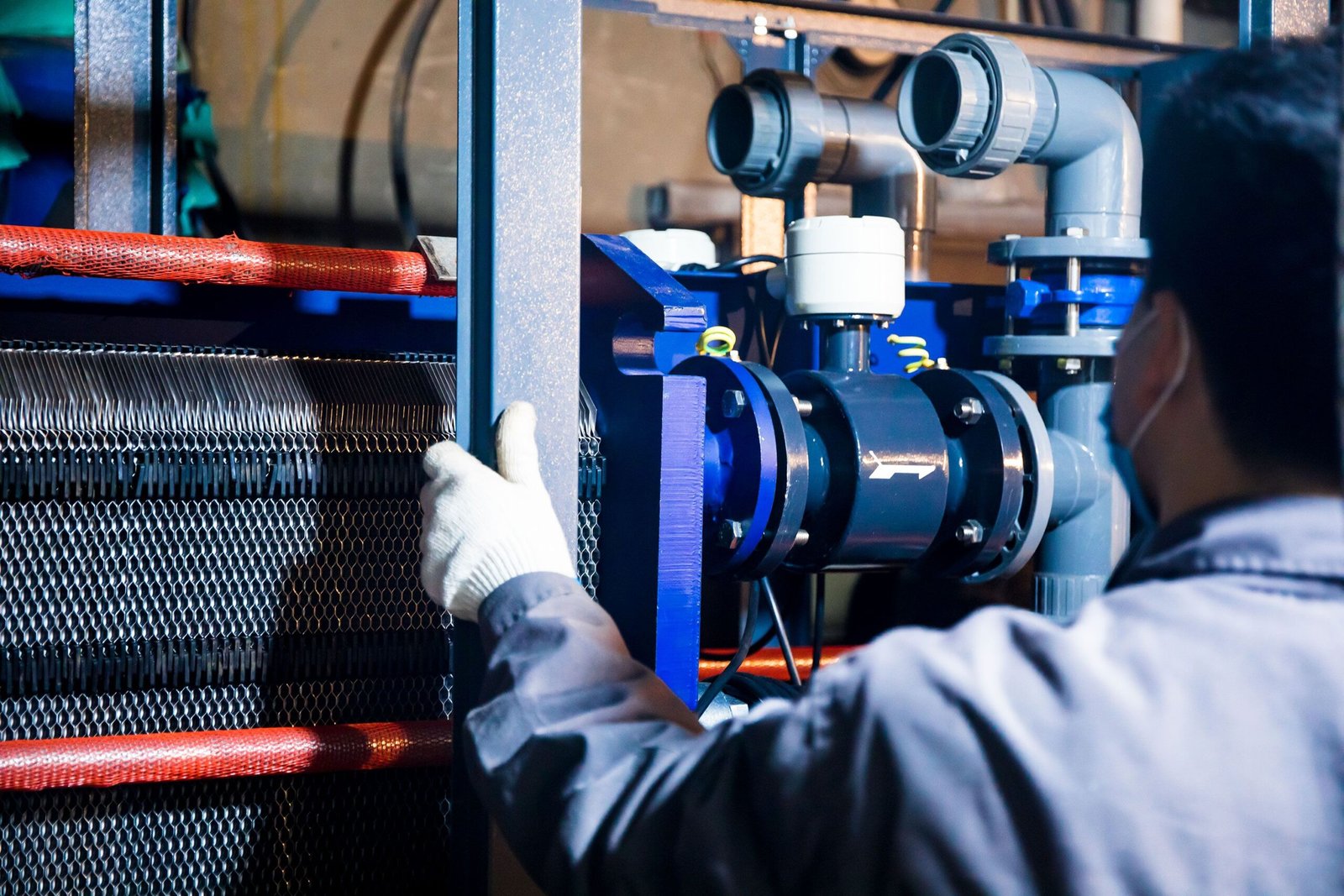 Common Mistakes in Heat Transfer Station Selection
The most common selection errors come from incomplete load data, excessive oversizing, incorrect pressure-drop assumptions, and failure to consider maintenance and future operating conditions.
Mistake 1: Selecting by building area alone
A simple W/m² assumption can be useful for preliminary estimation, but it is not sufficient for detailed equipment selection.
Avoid it: Use an actual heat-load calculation whenever possible.
Mistake 2: Using peak load without considering part-load operation
An oversized station may have difficulty maintaining stable temperatures at low load.
Avoid it: Check the control range and minimum operating load.
Mistake 3: Ignoring primary-side pressure
The heat exchanger and associated valves must withstand the actual design pressure.
Avoid it: Specify operating and design pressure separately.
Mistake 4: Allocating excessive pressure drop to the heat exchanger
A high-pressure-drop exchanger may reduce available pump margin.
Avoid it: Establish a pressure-drop budget for the complete station.
Mistake 5: Ignoring water quality
Poor water quality can cause:
- Scaling
- Corrosion
- Fouling
- Increased pressure drop
- Reduced heat-transfer capacity
Avoid it: Include water treatment and filtration requirements.
Mistake 6: Excessive oversizing
Oversizing can increase:
- Equipment cost
- Footprint
- Valve size
- Low-load control difficulty
Avoid it: Apply a justified design margin.
Mistake 7: Ignoring maintenance access
A heat exchanger may fit into the plant room but be impossible to open or service.
Avoid it: Check plate removal or tube-bundle access before finalizing the layout.
Mistake 8: Treating a replacement station as a direct copy
A new station may need to accommodate changes in:
- Heat load
- Temperatures
- Pressure
- Flow
- Control philosophy
- Regulations
Avoid it: Revalidate the complete system before selecting a replacement.
Heat Transfer Station Selection Checklist
Use this checklist before requesting a quotation or approving a heat transfer station design.
Load and thermal conditions
Peak heat load confirmed
Normal heat load confirmed
Minimum load considered
Future expansion considered
Primary inlet temperature confirmed
Primary outlet temperature confirmed
Secondary inlet temperature confirmed
Secondary outlet temperature confirmed
Temperature approach checked
Flow and hydraulic conditions
Primary flow rate calculated
Secondary flow rate calculated
Allowable primary pressure drop confirmed
Allowable secondary pressure drop confirmed
Pump head calculated
Control valve differential pressure checked
Strainer pressure drop considered
Heat exchanger
Heat exchanger type selected
Heat-transfer area calculated
Design pressure confirmed
Design temperature confirmed
Fouling allowance considered
Connection size confirmed
Connection orientation confirmed
Maintenance access checked
Materials
Plate/tube material selected
Shell material selected where applicable
Gasket material selected
Water chemistry reviewed
Corrosion risk evaluated
Cleaning chemical compatibility checked
Pumps and controls
Pump flow confirmed
Pump head confirmed
Pump efficiency reviewed
Variable-speed requirement confirmed
Control valve selected
Temperature sensors selected
Pressure sensors selected
Flow measurement requirements confirmed
Control logic defined
Compliance and commercial
Applicable certification identified
Material certificates specified
Pressure testing specified
Inspection requirements specified
Documentation package defined
Installation cost considered
Spare parts considered
Lead time confirmed
Lifecycle cost evaluated
FAQ
1. What is heat transfer station selection?
Heat transfer station selection is the process of choosing and sizing the heat exchanger, pumps, valves, controls, piping, safety devices, and other components needed to transfer heat reliably between a primary and secondary circuit.
2. What information is needed to select a heat transfer station?
At minimum, provide heat load, primary and secondary fluid types, flow rates, inlet and outlet temperatures, operating and design pressures, allowable pressure drops, installation conditions, control requirements, and material requirements.
3. How do you calculate the heat transfer station capacity?
For a sensible heating or cooling application:
[
Q=\dot{m}C_p\Delta T
]
For water, a preliminary volumetric-flow calculation can use:
[
Q(kW)\approx1.163\dot V(m^3/h)\Delta T(°C)
]
Final selection should use actual fluid properties and detailed heat exchanger calculations.
4. Which heat exchanger is best for a heat transfer station?
There is no universal best type. Gasketed plate heat exchangers are commonly attractive for compact hydronic systems, while shell-and-tube, brazed, or welded designs may be more suitable for particular pressure, temperature, fluid, fouling, or maintenance conditions.
5. How much pressure drop should a heat exchanger have?
There is no universal value. The allowable pressure drop depends on the available differential pressure, pump capacity, system design, energy cost, and required heat-transfer performance. The heat exchanger should be selected within the project’s specified pressure-drop limit.
6. Why is temperature approach important in heat transfer station selection?
A smaller temperature approach can improve heat recovery or heating performance but usually requires more heat-transfer area and may increase equipment cost. It should be optimized against capital and operating costs.
7. How does fouling affect heat transfer station sizing?
Fouling increases thermal resistance and can reduce heat-transfer capacity. High-fouling applications may require additional area, appropriate flow velocity, filtration, wider channels, or easier cleaning access.
8. How do I select a heat transfer station for district heating?
Start with the district-heating supply and return temperatures, building heating load, secondary supply and return temperatures, available primary pressure differential, allowable pressure drop, domestic hot-water requirements if applicable, control requirements, and required redundancy. Then size the heat exchanger, pumps, control valves, and safety equipment as an integrated system.
9. What materials should be used for a heat transfer station heat exchanger?
The material depends on fluid chemistry, temperature, pressure, corrosion risk, and cleaning conditions. Stainless steel is common in many water applications, while titanium, duplex stainless steel, carbon steel, copper alloys, or other materials may be appropriate for specific services.
10. Does a heat transfer station need certification?
It may. Requirements depend on the installation country, pressure category, application, equipment design, and project specification. Pressure equipment, material traceability, testing, inspection, and project-specific documentation should be evaluated before production.
11. How does heat transfer station selection affect operating cost?
Selection affects pump energy, heat-transfer efficiency, cleaning frequency, control stability, component life, and replacement requirements. A station with a lower initial price may have a higher lifecycle cost if it creates excessive pressure drop or requires frequent maintenance.
12. What should I check when replacing an existing heat transfer station?
Check the actual heat load, primary and secondary temperatures, flow rates, pressure, pressure drop, heat exchanger type, materials, connections, pump capacity, control valves, sensors, physical dimensions, certification, and maintenance requirements. Do not select a replacement based only on the old model number or dimensions.
Key Takeaways
- Heat transfer station selection should start with actual heat load and operating conditions, not equipment size alone.
- Primary and secondary flow rates, temperatures, pressures, and allowable pressure drops are the core selection parameters.
- The heat exchanger must be sized for both thermal duty and hydraulic performance.
- Gasketed plate, brazed plate, welded plate, and shell-and-tube heat exchangers have different advantages, limitations, and maintenance requirements.
- Temperature approach, fouling, pressure drop, and material compatibility can significantly affect both initial cost and long-term performance.
- Pumps, control valves, sensors, and automation should be selected as part of the complete heat transfer station rather than separately.
- Certification, material traceability, pressure testing, maintenance access, and spare parts should be defined before production.
- The most economical heat transfer station is the one that meets the required thermal and hydraulic performance with an appropriate lifecycle cost, not necessarily the one with the lowest purchase price.