A heat transfer unit works by transferring heat from one fluid circuit to another through a heat exchanger while pumps, valves, sensors, controls, and other components regulate the process. The two fluids normally remain separated, and heat passes through a conductive heat-transfer surface such as plates or tubes.
Understanding the heat transfer unit working principle is important when selecting, sizing, operating, troubleshooting, or replacing a complete heat transfer system. A heat exchanger alone transfers heat, but a complete heat transfer unit controls how much heat is transferred, at what temperature, at what flow rate, and under what pressure conditions.
This guide explains how a heat transfer unit works, how heat moves through the system, how temperature and flow are controlled, how to size the main components, and which problems commonly reduce performance.
Table of Contents
- Quick Answer: What Is the Working Principle of a Heat Transfer Unit?
- How Does a Heat Transfer Unit Transfer Heat?
- What Are the Main Components of a Heat Transfer Unit?
- How Does Temperature Control Work?
- How Do Flow Rate and Pressure Drop Affect Performance?
- How Is a Heat Transfer Unit Sized and Selected?
- How Do Different Heat Exchanger Types Affect the System?
- How to Select a Heat Transfer Unit Step by Step
- Common Mistakes in Heat Transfer Unit Design and Operation
- Heat Transfer Unit Selection Checklist
- FAQ
- Key Takeaways
Quick Answer: What Is the Working Principle of a Heat Transfer Unit?
A heat transfer unit transfers thermal energy between two separate fluid circuits through a heat exchanger while pumps, control valves, sensors, and automation maintain the required temperature and flow conditions.
A typical system works as follows:
Heat source → primary circulation → heat exchanger → secondary circulation → end users
For a heating application, for example:
- A hot primary fluid enters the heat exchanger.
- A secondary fluid enters the opposite side.
- Heat passes through the heat-transfer surface.
- The primary fluid leaves at a lower temperature.
- The secondary fluid leaves at a higher temperature.
- Temperature sensors measure actual conditions.
- A control valve adjusts the primary flow to match the heat demand.
- Pumps maintain the required circulation.
The basic heat-transfer equation is:
[
Q = U A \Delta T_{lm}
]
Where:
- Q = heat-transfer duty
- U = overall heat-transfer coefficient
- A = heat-transfer area
- ΔTlm = log mean temperature difference
The complete unit must satisfy both thermal requirements and hydraulic requirements.
How Does a Heat Transfer Unit Transfer Heat?
Heat transfer occurs when two fluids at different temperatures flow through separate passages and thermal energy moves through the separating heat-transfer wall.
What happens inside the heat exchanger?
Consider a plate heat exchanger.
The hot fluid enters one side while the cold fluid enters the other side. The fluids flow through separate channels created by the plates.
The heat-transfer process has three basic stages:
- Heat moves from the hot fluid to the hot-side wall.
- Heat conducts through the metal plate.
- Heat moves from the plate to the cold fluid.
The fluids do not normally mix.
Counterflow operation
Counterflow is widely used because it can provide an effective temperature driving force along the heat exchanger.
A simplified arrangement is:
Hot fluid:   → → → → →
Cold fluid:  ← ← ← ← ←
The temperature difference between the two fluids remains relatively effective across the heat exchanger.
Parallel-flow operation
In parallel flow, both fluids travel in the same direction:
Hot fluid:   → → → → →
Cold fluid:  → → → → →
The temperature difference usually decreases more rapidly along the flow path.
Counterflow vs. parallel flow
| Factor | Counterflow | Parallel flow |
|---|---|---|
| Thermal efficiency | Generally higher | Generally lower |
| Temperature approach | Can achieve closer approach | More limited |
| Heat-transfer area | Often more efficient | May require more area |
| Common industrial use | Very common | Used for specific applications |
| Temperature control | Often favorable | Application dependent |
What determines heat-transfer performance?
Important factors include:
- Temperature difference
- Flow rate
- Fluid properties
- Heat-transfer coefficient
- Heat-transfer area
- Channel/tube geometry
- Fluid velocity
- Material thermal conductivity
- Fouling resistance
- Flow arrangement
Increasing flow velocity can improve heat transfer, but it can also increase pressure drop.
Therefore, heat exchanger design is always a balance between thermal performance and hydraulic performance.
What Are the Main Components of a Heat Transfer Unit?
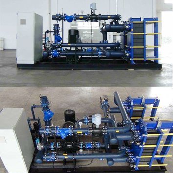
A complete heat transfer unit normally combines a heat exchanger with circulation, control, measurement, safety, and connection components.
The exact configuration depends on the application.
Main components
A typical packaged unit may include:
- Heat exchanger
- Primary-side pump or circulation connection
- Secondary-side pump
- Control valve
- Temperature sensors
- Pressure gauges
- Pressure sensors
- Flow meter
- Expansion vessel where required
- Safety valve
- Isolation valves
- Check valves
- Strainer
- Air separator
- Drain and vent connections
- Control cabinet
- PLC or other controller
- Piping and skid/frame
Component functions
| Component | Main function |
|---|---|
| Heat exchanger | Transfers thermal energy |
| Pump | Provides fluid circulation |
| Control valve | Regulates heating/cooling capacity |
| Temperature sensor | Measures fluid temperature |
| Pressure sensor | Monitors system pressure |
| Flow meter | Measures flow rate |
| Strainer | Protects components from debris |
| Safety valve | Protects against excessive pressure |
| Check valve | Prevents reverse flow |
| Expansion vessel | Accommodates fluid volume changes |
| Controller | Coordinates system operation |
| Frame/skid | Supports and integrates components |
The heat exchanger is the core heat-transfer component, but the control system determines how the unit responds to changing demand.
How Does Temperature Control Work?
Temperature is usually controlled by adjusting the amount of hot or cold primary fluid flowing through the heat exchanger.
Basic control principle
Suppose a secondary heating circuit needs water at 60°C.
The system continuously measures the secondary outlet temperature.
If the temperature falls below the setpoint:
Increase primary hot-fluid flow → increase heat transfer → outlet temperature rises.
If the temperature rises above the setpoint:
Reduce primary hot-fluid flow → reduce heat transfer → outlet temperature falls.
A modulating control valve is commonly used for this purpose.
Two-way vs. three-way control
| Control method | Typical use | Main characteristic |
|---|---|---|
| Two-way valve | Variable-load systems | Adjusts primary flow |
| Three-way valve | Mixing/diverting applications | Controls temperature through mixing or bypass |
| Variable-speed pump | Variable-flow systems | Adjusts circulation flow |
| Combined valve + pump control | Advanced systems | Coordinates thermal and hydraulic demand |
Why is control stability important?
A heat transfer unit may have enough heat-transfer capacity but still operate poorly if the control system is unstable.
Common symptoms include:
- Temperature oscillation
- Valve hunting
- Excessive pump cycling
- Slow response
- Temperature overshoot
- Uneven heating or cooling
Control parameters should therefore be selected according to:
- System volume
- Heat exchanger response
- Valve characteristics
- Sensor location
- Flow rate
- Load variation
How Do Flow Rate and Pressure Drop Affect Performance?
Flow rate directly affects heat-transfer capacity, while pressure drop determines how much pumping energy is required to move the fluid through the heat exchanger.
Flow rate and heat transfer
For a fluid circuit:
[
Q = \dot{m} C_p \Delta T
]
Where:
- Q = heat duty
- ṁ = mass flow rate
- Cp = specific heat capacity
- ΔT = fluid temperature change
This means that increasing flow rate can increase heat-transfer capacity when other conditions remain suitable.
However, flow rate cannot be increased without considering pressure drop.
What is pressure drop?
Pressure drop is the difference between inlet and outlet pressure caused by flow resistance.
It depends on:
- Flow rate
- Fluid viscosity
- Fluid density
- Channel geometry
- Tube diameter
- Plate pattern
- Number of passes
- Pipe length
- Fittings
Thermal performance vs. pressure drop
| Design approach | Thermal effect | Hydraulic effect |
|---|---|---|
| Higher velocity | Often improves heat transfer | Increases pressure drop |
| Larger channels | May reduce heat-transfer coefficient | Reduces pressure drop |
| More passes | Can improve velocity/heat transfer | May increase pressure drop |
| Larger heat exchanger | More area | Can reduce required velocity |
| Smaller heat exchanger | Lower initial cost | May require higher velocity |
The design target is not maximum heat transfer at any cost.
It is the required heat duty within the available pressure-drop limit.
How Is a Heat Transfer Unit Sized and Selected?
Heat transfer unit sizing starts with heat duty and operating conditions, then checks heat-transfer area, temperature approach, pressure drop, materials, control requirements, and mechanical limits.
Required design information
A supplier or application engineer normally needs:
Primary side
- Fluid type
- Flow rate
- Inlet temperature
- Outlet temperature
- Operating pressure
- Design pressure
- Operating temperature
- Design temperature
Secondary side
- Fluid type
- Flow rate
- Inlet temperature
- Outlet temperature
- Operating pressure
- Design pressure
- Operating temperature
- Design temperature
Project requirements
- Maximum allowable pressure drop
- Installation space
- Connection size
- Connection orientation
- Material requirements
- Certification
- Control requirements
- Cleaning requirements
- Ambient conditions
Step 1: Calculate heat duty
For a sensible heating or cooling application:
[
Q = \dot{m} C_p (T_{out}-T_{in})
]
For example, if water flows at:
- Mass flow = 10 kg/s
- Cp ≈ 4.18 kJ/kg·K
- Temperature rise = 10 K
Then:
[
Q = 10 \times 4.18 \times 10
]
[
Q \approx 418\text{ kW}
]
The actual design should use the appropriate fluid properties at the relevant temperatures.
Step 2: Calculate temperature driving force
For counterflow heat exchange:
[
\Delta T_{lm} =
\frac{\Delta T_1-\Delta T_2}
{\ln(\Delta T_1/\Delta T_2)}
]
The temperature differences must be defined correctly for the selected flow arrangement.
Step 3: Estimate heat-transfer area
A simplified calculation is:
[
A = \frac{Q}{U\Delta T_{lm}}
]
The actual value of U depends on the fluids, materials, geometry, flow regime, and fouling conditions.
Step 4: Check pressure drop
Confirm that the calculated pressure drop is within the available system allowance.
Step 5: Select materials
Review:
- Corrosion
- Temperature
- Pressure
- Fluid chemistry
- Cleaning chemicals
- Fouling
- Erosion
Step 6: Select controls
Determine:
- Valve type
- Sensor locations
- Pump control
- Setpoints
- Control logic
- Communication requirements
Step 7: Verify mechanical integration
Check:
- Connections
- Dimensions
- Weight
- Service space
- Drainage
- Venting
- Maintenance access
How Do Different Heat Exchanger Types Affect the System?
The heat exchanger type changes the thermal performance, pressure drop, maintenance method, cost, and suitable operating range of the complete heat transfer unit.
Gasketed plate heat exchanger
Gasketed plate heat exchangers use removable plates and gaskets.
Typical advantages:
- Compact design
- High heat-transfer coefficient
- Easy internal inspection
- Plate expansion possible on many models
- Flexible maintenance
Potential limitations:
- Gasket temperature limitations
- Gasket chemical compatibility
- Narrow channels may be sensitive to fouling
- Periodic gasket replacement may be required
Brazed plate heat exchanger
Brazed units have plates permanently joined through brazing.
Typical advantages:
- Compact
- Low material volume
- No conventional removable gasket
- Suitable for many HVAC and refrigeration applications
Potential limitations:
- Limited internal accessibility
- Cleaning options depend on the design and application
- Replacement is often preferred if internal blockage is severe
Welded plate heat exchanger
Welded construction eliminates conventional gaskets in the welded section.
It may be useful for:
- Higher temperatures
- Certain aggressive fluids
- Applications where gasket compatibility is difficult
Shell-and-tube heat exchanger
Shell-and-tube units use a tube bundle inside a shell.
Advantages include:
- Established technology
- Broad application range
- Suitable for many high-pressure and high-temperature services
- Tube-side cleaning can be practical depending on construction
Heat exchanger comparison
| Type | Compactness | Maintenance access | Typical application |
|---|---|---|---|
| Gasketed plate | High | Excellent | HVAC, industrial heating/cooling |
| Brazed plate | Very high | Limited | Refrigeration, HVAC, compact systems |
| Welded plate | High | Application dependent | Process and demanding services |
| Shell-and-tube | Medium | Good, depending on design | Process, power, industrial systems |
No type is universally superior. Selection should be based on the fluid, pressure, temperature, fouling, maintenance method, space, and lifecycle cost.
How to Select a Heat Transfer Unit Step by Step
A reliable selection process starts with process data rather than choosing a heat exchanger model first.
Step 1: Define the heat source and heat demand
Identify:
- Heat source
- Heat consumer
- Required duty
- Load variation
- Operating schedule
Step 2: Collect fluid data
Record:
- Fluid name
- Concentration
- Density
- Specific heat
- Viscosity
- Thermal conductivity
- Corrosive components
- Solid content
For water-glycol systems, for example, the glycol concentration affects viscosity, heat capacity, pressure drop, and heat-transfer performance.
Step 3: Define temperature conditions
Record:
- Primary inlet temperature
- Primary outlet temperature
- Secondary inlet temperature
- Secondary outlet temperature
Then determine the required temperature approach.
Step 4: Define pressure conditions
Record:
- Operating pressure
- Design pressure
- Maximum allowable pressure drop
- Relief conditions where applicable
Step 5: Select heat exchanger technology
Compare:
- Gasketed plate
- Brazed plate
- Welded plate
- Shell-and-tube
- Custom OEM design
Step 6: Select materials
Evaluate:
- Plates or tubes
- Shell
- Connections
- Gaskets
- Brazing material
- Corrosion environment
Step 7: Perform thermal and hydraulic calculations
Confirm:
- Heat duty
- Heat-transfer area
- Temperature approach
- Pressure drop
- Fouling allowance
Step 8: Design the control system
Determine:
- Control valve
- Pump
- Sensors
- Controller
- Actuator
- Control logic
Step 9: Check maintenance requirements
Consider:
- Cleaning frequency
- Gasket replacement
- Tube cleaning
- Spare parts
- Isolation valves
- Drainage
- Access space
Step 10: Review compliance and documentation
Confirm:
- Applicable regulations
- Pressure equipment requirements
- Material certificates
- Testing
- Inspection
- Documentation package
 Common Mistakes in Heat Transfer Unit Design and Operation
 Common Mistakes in Heat Transfer Unit Design and Operation
Most heat transfer unit problems result from incomplete operating data, incorrect sizing, poor control, unsuitable materials, or inadequate maintenance planning.
Mistake 1: Sizing only by heat exchanger capacity
A heat exchanger may meet the heat duty while exceeding the allowable pressure drop.
Avoid it: Always check thermal and hydraulic performance together.
Mistake 2: Using operating pressure as design pressure
Normal operating pressure may not represent the maximum pressure the equipment must withstand.
Avoid it: Define design pressure separately.
Mistake 3: Ignoring fouling
A clean heat exchanger calculation may perform well initially and gradually lose capacity.
Avoid it: Include realistic fouling resistance and establish a cleaning strategy.
Mistake 4: Choosing material based only on fluid name
“Water” is not a sufficient material-selection specification.
Water chemistry, temperature, chlorides, oxygen, pH, and contaminants can change corrosion behavior.
Avoid it: Evaluate the actual fluid chemistry.
Mistake 5: Selecting a small temperature approach without checking cost
A very small approach can substantially increase heat-transfer area.
Avoid it: Compare capital cost and operating savings.
Mistake 6: Installing sensors in poor locations
A sensor located too far from the heat exchanger or in a poorly mixed section may provide misleading temperature information.
Avoid it: Position sensors where they accurately represent the controlled process.
Mistake 7: Ignoring air and debris
Air pockets and debris can reduce heat-transfer performance and increase pressure drop.
Avoid it: Consider air separation, venting, strainers, and flushing during system design.
Mistake 8: Choosing a replacement only by dimensions
A replacement unit may physically fit but have different:
- Heat-transfer capacity
- Pressure drop
- Pressure rating
- Material
- Gasket
- Connection configuration
Avoid it: Perform a complete replacement selection.
Heat Transfer Unit Selection Checklist
Use this checklist before ordering or approving a heat transfer unit.
Thermal
Required heat duty confirmed
Primary flow rate confirmed
Secondary flow rate confirmed
Primary inlet/outlet temperatures confirmed
Secondary inlet/outlet temperatures confirmed
Temperature approach checked
Heat-transfer area confirmed
Fouling allowance included
Hydraulic
Primary pressure drop checked
Secondary pressure drop checked
Pump capacity checked
Flow velocity reviewed
Maximum allowable pressure drop confirmed
Mechanical
Operating pressure confirmed
Design pressure confirmed
Operating temperature confirmed
Design temperature confirmed
Connection sizes confirmed
Connection orientation confirmed
Installation dimensions confirmed
Maintenance space confirmed
Materials
Plate/tube material selected
Shell material selected where applicable
Gasket material selected
Corrosion compatibility checked
Cleaning chemical compatibility checked
Controls
Temperature sensors specified
Pressure sensors specified
Flow measurement specified if required
Control valve selected
Actuator selected
Controller/PLC requirements defined
Communication protocol confirmed if required
Maintenance and compliance
Cleaning method defined
Spare parts identified
Applicable certification identified
Pressure testing requirements confirmed
Material certificates confirmed
Documentation package confirmed
FAQ
1. What is a heat transfer unit?
A heat transfer unit is an integrated system that transfers thermal energy between fluid circuits and normally includes a heat exchanger, pumps, control valves, sensors, piping, safety components, and controls.
2. What is the working principle of a heat transfer unit?
A heat transfer unit circulates two separate fluids through a heat exchanger. Heat moves from the hotter fluid through a conductive heat-transfer surface to the colder fluid while pumps and control valves regulate flow and temperature.
3. What is the difference between a heat exchanger and a heat transfer unit?
A heat exchanger is the component that transfers heat. A heat transfer unit is a larger integrated system that can include the heat exchanger, pumps, valves, sensors, controls, piping, and safety equipment.
4. How do you calculate heat transfer unit capacity?
For a sensible heating or cooling application:
[
Q=\dot{m}C_p\Delta T
]
The heat exchanger itself can then be evaluated using:
[
Q=UA\Delta T_{lm}
]
Actual sizing should account for fluid properties, fouling, flow arrangement, pressure drop, and design conditions.
5. Why is counterflow heat exchange commonly used?
Counterflow can maintain a favorable temperature driving force across the heat exchanger and can achieve a smaller temperature approach than many equivalent parallel-flow arrangements.
6. How does flow rate affect heat exchanger performance?
Higher flow can increase heat-transfer coefficients and capacity, but it also generally increases pressure drop. The correct flow rate must balance thermal performance and hydraulic limitations.
7. How does fouling affect a heat transfer unit?
Fouling adds thermal resistance, reducing the overall heat-transfer coefficient. It can cause higher pressure drop and lower outlet temperatures, eventually requiring cleaning or replacement.
8. Which is better, a plate heat exchanger or a shell-and-tube heat exchanger?
Neither is universally better. Plate heat exchangers are often attractive where compactness and high heat-transfer efficiency are important, while shell-and-tube units can be advantageous for certain high-pressure, high-temperature, or process applications.
9. How do you choose a heat transfer unit for HVAC?
Start with heating or cooling duty, water flow, inlet/outlet temperatures, allowable pressure drop, system pressure, space, control requirements, and water chemistry. Then select the heat exchanger type, materials, pump, valve, and controls.
10. Can a heat transfer unit use glycol?
Yes. Water-glycol mixtures are commonly used in appropriate heating and cooling systems. However, glycol concentration affects viscosity, specific heat, pressure drop, and heat-transfer performance, so the actual concentration must be included in sizing.
11. What causes a heat transfer unit to lose heating capacity?
Common causes include fouling, insufficient flow, air in the system, incorrect control-valve operation, inadequate heat-source temperature, incorrect sizing, blocked channels, pump problems, and changes in fluid properties.
12. How often should a heat transfer unit be maintained?
There is no universal maintenance interval. Frequency depends on fluid cleanliness, fouling tendency, operating hours, temperature, water chemistry, and system criticality. Monitoring outlet temperature, pressure drop, flow, and heat-transfer performance can help establish a condition-based maintenance schedule.
Key Takeaways
- A heat transfer unit combines a heat exchanger with pumps, valves, sensors, controls, piping, and safety components to deliver controlled thermal energy.
- Heat transfer is primarily governed by heat duty, heat-transfer area, overall heat-transfer coefficient, and temperature driving force.
- Flow rate and pressure drop must be evaluated together because increasing velocity can improve heat transfer while increasing pumping requirements.
- Temperature approach has a major effect on heat exchanger size and therefore equipment cost.
- Material selection must consider fluid chemistry, temperature, pressure, corrosion, fouling, and cleaning conditions.
- Gasketed, brazed, welded plate, and shell-and-tube heat exchangers have different performance and maintenance characteristics.
- Correct sizing requires both thermal and hydraulic calculations, not heat duty alone.
- A reliable heat transfer unit should be designed around actual operating conditions, maintenance requirements, control strategy, and applicable certification requirements.