Choosing the right heat exchanger starts with five parameters: duty (kW), flow rates, allowable pressure drop, temperature approach, and fluid properties including fouling tendency and corrosiveness. Match these to the correct type — plate, shell and tube, brazed, or welded — then confirm material, gasket, and certification requirements before ordering. This guide gives you the selection logic, formulas, comparison tables, and checklists that engineers and procurement teams actually use, so you can specify a unit that performs, lasts, and fits your budget.
Quick Answer Box
Clean fluids, tight approach, compact space → gasketed plate heat exchanger (PHE)
High pressure/temperature, dirty fluids, easy tube cleaning → shell and tube
No gaskets, small footprint, refrigeration/HVAC → brazed plate (BPHE)
Aggressive chemicals, high temperature, zero leakage → welded or all-welded plate
Always specify: duty, flow rates, inlet/outlet temperatures, pressure drop limit, material, connection size, and certification.
Table of Contents
What Is a Heat Exchanger and How Does Selection Work?
Step-by-Step Guide: How to Select a Heat Exchanger
Heat Exchanger Types Compared
Key Selection Parameters and Formulas
Material Selection: Plates, Tubes, Gaskets
Pressure Drop, Fouling, and Temperature Approach
Cost, Lead Time, and Certification Factors
Installation and Maintenance Checklist
Common Mistakes and How to Avoid Them
FAQ
Key Takeaways
What Is a Heat Exchanger and How Does Selection Work?
A heat exchanger is a device that transfers heat between two fluids without mixing them. Selection means matching the thermal duty, hydraulic limits, fluid chemistry, and mechanical constraints to the most economical type and size.
There are three questions every buyer must answer before requesting a quote:
What is the duty? Heat load in kW, plus inlet and outlet temperatures on both sides.
What are the fluids? Water, glycol, oil, steam, refrigerant, seawater, chemical, food product, or gas.
What are the limits? Maximum pressure drop, available space, pressure/temperature rating, and connection size.
If you cannot answer these, any quotation you receive is a guess. A good supplier will ask for them — a serious one will refuse to quote without them.
Step-by-Step Guide: How to Select a Heat Exchanger
Follow these eight steps in order. Each one filters the options until one design remains.
Step 1: Define the Thermal Duty
Calculate the required heat load:
Q = m × cp × ΔT
Where:
Q = heat duty (kW)
m = mass flow rate (kg/s)
cp = specific heat (kJ/kg·K)
ΔT = temperature change (K)
For phase change (steam, refrigerant), use latent heat instead.
Step 2: Establish the Temperature Program
List all four temperatures:
Hot side in / out
Cold side in / out
Calculate the LMTD (log mean temperature difference) and then the corrected MTD using the F-factor for your flow arrangement.
Step 3: Estimate the Overall Heat Transfer Coefficient (U)
Use typical starting values:
| Service | Typical U (W/m²·K) |
|---|---|
| Water–water (plate) | 3,000–7,000 |
| Water–water (shell & tube) | 800–1,500 |
| Steam–water | 2,000–4,500 |
| Oil–water | 300–900 |
| Gas–gas | 20–200 |
| Refrigerant–water (BPHE) | 2,000–5,000 |
Step 4: Calculate Required Area
A = Q / (U × LMTD × F)
This gives the heat transfer area. Add 10–20% fouling margin for dirty service.
Step 5: Select the Type
Use the decision table in the next section. Match fluid cleanliness, pressure, temperature, and maintenance access to the exchanger type.
Step 6: Check Pressure Drop
Confirm both sides are within allowable pressure drop — typically:
20–50 kPa for water circuits
50–100 kPa for oil circuits
Lower for gravity or pump-limited systems
High pressure drop means more pumping cost. Low pressure drop means a larger, more expensive unit.
Step 7: Choose Materials
Match plate/tube and gasket material to fluid chemistry. See the material section below.
Step 8: Confirm Certification and Documentation
For export projects, confirm:
PED (Europe)
ASME (North America)
CRN (Canada)
CE marking
Third-party inspection (TÜV, SGS, BV)
Material certificates (EN 10204 3.1)
Heat Exchanger Types Compared
Each type wins in specific applications. There is no universal “best.”
Comparison Table 1: Type Selection Matrix
| Feature | Gasketed PHE | Brazed (BPHE) | Welded Plate | Shell & Tube |
|---|---|---|---|---|
| Max pressure | 25 bar | 30–45 bar | 40 bar | 100+ bar |
| Max temperature | 180°C | 200°C | 350°C | 500°C+ |
| Temperature approach | 1–2 K | 1–2 K | 2–3 K | 5–10 K |
| Fouling resistance | Low | Low | Medium | High |
| Cleaning | Easy (open) | Not cleanable | CIP only | Mechanical |
| Footprint | Very compact | Very compact | Compact | Large |
| Gasket risk | Yes | None | None | None (or limited) |
| Relative cost | Medium | Low | High | Medium–High |
| Best for | HVAC, food, general | Refrigeration, OEM | Chemicals, high temp | Steam, dirty, high P |
When to Choose Each Type
Gasketed plate heat exchanger
Clean fluids on both sides
Tight temperature approach required
Space is limited
Future capacity increase needed (add plates)
Brazed plate heat exchanger
Refrigeration, heat pumps, chillers
No gasket compatibility concerns
OEM volume production
Compact, sealed, maintenance-free
Welded / all-welded plate
Aggressive chemicals
High temperature
Zero cross-contamination risk
No elastomer gaskets
Shell and tube
High pressure and temperature
Dirty or fouling fluids
Steam condensation
Mechanical cleaning required
Key Selection Parameters and Formulas
Heat Transfer Fundamentals
| Parameter | Formula | Notes |
|---|---|---|
| Heat duty | Q = m·cp·ΔT | kW |
| LMTD | (ΔT1 − ΔT2) / ln(ΔT1/ΔT2) | Counter-current |
| Area | A = Q / (U·LMTD·F) | m² |
| Reynolds number | Re = ρ·v·D/μ | Turbulence indicator |
| Pressure drop | ΔP = f·(L/D)·(ρv²/2) | Per side |
| NTU | UA / (m·cp)min | Effectiveness method |
Flow Rate and Velocity Limits
| Fluid | Recommended velocity |
|---|---|
| Water (plate) | 0.3–1.0 m/s |
| Water (tube) | 1.0–2.5 m/s |
| Seawater | 1.0–2.0 m/s |
| Oil | 0.5–1.5 m/s |
| Steam | 15–40 m/s |
| Gas | 10–30 m/s |
Too low = fouling and poor distribution. Too high = erosion and excessive pressure drop.
Material Selection: Plates, Tubes, Gaskets
Material selection is where most projects fail. A correct thermal design with the wrong material will corrode in months.
Comparison Table 2: Material Selection Guide
| Fluid / Environment | Plate or Tube | Gasket |
|---|---|---|
| Clean water, HVAC | 316L stainless | NBR |
| Treated water, glycol | 316L | EPDM |
| Seawater | Titanium, SMO 254 | EPDM / Viton |
| Steam | 316L | EPDM / Viton |
| Ammonia | 316L | NBR (not copper) |
| Food / dairy | 316L | EPDM (FDA) |
| Acids (dilute) | SMO 254, titanium | PTFE |
| Oils, hydrocarbons | 316L, carbon steel | Viton |
| High-chloride | Titanium | Viton |
Notes on Materials
316L stainless covers most water and process duty.
Titanium is standard for seawater and high-chloride service.
SMO 254 handles sulfuric and phosphoric acid better than 316L.
Copper brazing in BPHEs is not compatible with ammonia; use nickel brazing.
Gasket choice matters: NBR for oils and ammonia, EPDM for hot water and steam, Viton for high temperature and chemicals.
Pressure Drop, Fouling, and Temperature Approach
These three factors drive both performance and cost. Ignoring any one leads to oversized pumps, frequent cleaning, or an undersized unit.
Pressure Drop
Pressure drop rises with the square of flow velocity.
Doubling flow roughly quadruples pressure drop.
Specify a limit before design, not after.
Fouling
Fouling is the build-up of deposits on heat transfer surfaces. It reduces U and increases pressure drop.
| Fouling Type | Cause | Mitigation |
|---|---|---|
| Scaling | Hard water, high temp | Softening, lower temp |
| Biofouling | Bacteria, algae | Chlorination, velocity |
| Particulate | Suspended solids | Filtration, strainer |
| Corrosion | Aggressive fluid | Material upgrade |
| Chemical | Reaction deposits | CIP, additives |
Fouling factors (m²·K/W):
Clean water: 0.00005
Cooling tower water: 0.0002
Seawater: 0.0001
Oil: 0.0004
Steam: 0.0001
Temperature Approach
Temperature approach is the smallest difference between hot and cold outlet temperatures.
PHE can achieve 1–2 K approach.
Shell and tube typically 5–10 K.
Tighter approach = larger area = higher cost, but better energy recovery.
Ask yourself: is the energy saving worth the extra surface? For heat recovery projects, often yes. For simple cooling, usually no.
 Cost, Lead Time, and Certification Factors
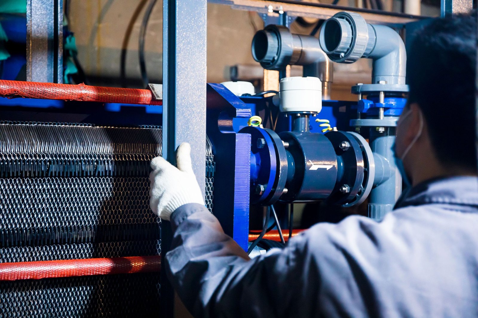 Cost, Lead Time, and Certification Factors
Cost Factors
| Factor | Impact on Cost |
|---|---|
| Surface area | Linear increase |
| Material (Ti, SMO) | 2–5× vs 316L |
| Pressure rating | Higher class = higher cost |
| Gasket type | Viton/PTFE > EPDM > NBR |
| Certification | PED/ASME adds 5–15% |
| Special connections | Flanges, hygienic, welded |
| OEM volume | 10–30% reduction at scale |
Lead Time Factors
Standard gasketed PHE: 2–4 weeks
Custom plate PHE: 4–8 weeks
Brazed plate (standard): 2–5 weeks
Shell and tube (custom): 6–12 weeks
Welded plate: 6–10 weeks
With PED/ASME + third-party inspection: add 1–3 weeks
Ordering spare plates and gaskets in advance reduces downtime risk.
Certification Factors
For export to Europe, North America, and the Middle East, confirm:
PED 2014/68/EU — mandatory for Europe
ASME U / UM stamp — common for North America
CRN — required in Canadian provinces
CE marking — machine or pressure directive
ATEX — for explosive atmospheres
FDA / EHEDG — food and pharmaceutical
Marine class — DNV, Lloyd’s, ABS for ships
Material traceability — EN 10204 3.1 certificates
Never accept a certificate you cannot verify. Ask for the issuing body and certificate number.
Installation and Maintenance Checklist
Use this checklist before commissioning and during routine service.
Pre-Installation
- □
Verify nameplate matches design data
- □
Check flange ratings and gasket type
- □
Confirm flow direction (counter-current preferred)
- □
Install strainers upstream (≤1 mm mesh)
- □
Provide isolation valves and bypass
- □
Install pressure gauges and thermometers on all four ports
- □
Confirm foundation or mounting supports
- □
Check electrical/Instrument connections if applicable
Commissioning
- □
Flush system before connecting
- □
Tighten flange bolts to specified torque
- □
Open valves slowly to avoid water hammer
- □
Vent air from high points
- □
Record initial pressure drop and temperatures
- □
Check for leaks at gaskets and connections
Routine Maintenance
- □
Log pressure drop and temperatures weekly
- □
Inspect for leaks monthly
- □
Clean strainers as needed
- □
CIP clean plate units per schedule
- □
Replace gaskets when hardening or leaking
- □
Re-torque bolts after thermal cycling
- □
Keep spare plates and gaskets on shelf
Common Mistakes and How to Avoid Them
These are the errors that cause real project failures.
1. Specifying Only Duty Without Pressure Drop Limit
Problem: Vendor quotes a unit with 150 kPa pressure drop. Your pump cannot handle it.
Fix: Always state allowable pressure drop on both sides.
2. Ignoring Fouling Margin
Problem: Unit performs well when new, then fails after 6 months.
Fix: Add 10–20% area margin for dirty service. Use correct fouling factors.
3. Wrong Gasket Material
Problem: EPDM gasket swells in oil service.
Fix: Match gasket to fluid: NBR for oil/ammonia, EPDM for water/steam, Viton for high temp.
4. Choosing Titanium When 316L Is Enough
Problem: 3× cost with no benefit.
Fix: Use titanium only for chloride or seawater service.
5. Undersizing Connections
Problem: High velocity and noise at nozzles.
Fix: Size connections to keep velocity within limits.
6. No Space for Maintenance
Problem: Cannot open plate pack or pull tube bundle.
Fix: Leave clearance for plate opening or tube extraction.
7. Buying on Price Alone
Problem: Cheap unit fails in 12 months, replacement cost exceeds savings.
Fix: Compare total cost of ownership: efficiency, maintenance, downtime, spare parts.
8. Missing Certification for Destination Country
Problem: Shipment held at customs.
Fix: Confirm PED, ASME, CRN, or local requirements before ordering.
9. No Spare Parts Plan
Problem: Weeks of downtime waiting for gaskets.
Fix: Order spare gasket set and 2–5% spare plates with the original unit.
10. Not Matching Replacement Parts Correctly
Problem: Replacement plate or gasket does not fit.
Fix: Send nameplate photos, plate drawings, or part numbers for verification.
FAQ
1. What is the most important factor when selecting a heat exchanger?
The most important factor is the fluid properties and duty — specifically the flow rates, temperatures, and fouling tendency. These determine the type, size, and material.
2. How do I choose between a plate heat exchanger and a shell and tube?
Choose a plate heat exchanger for clean fluids, tight temperature approach, and compact space. Choose shell and tube for high pressure/temperature, dirty fluids, or when mechanical cleaning is required.
3. What is temperature approach and why does it matter?
Temperature approach is the smallest temperature difference between the hot and cold fluid outlets. A tighter approach (1–2 K) recovers more heat but requires more surface area and higher cost.
4. How much pressure drop is acceptable in a heat exchanger?
Typical limits are 20–50 kPa for water circuits and 50–100 kPa for oil circuits. Always specify the limit before design to avoid pump problems.
5. What material should I use for a seawater heat exchanger?
Use titanium plates or tubes with EPDM or Viton gaskets. 316L stainless will corrode in seawater.
6. Can a brazed plate heat exchanger be repaired?
Generally no. Brazed units are sealed and not cleanable. If fouling or corrosion occurs, the unit is usually replaced. For repairable service, choose gasketed or welded plate.
7. How do I size a heat exchanger for a chiller or heat pump?
Use the refrigeration duty, refrigerant type, and water flow rates. BPHEs are standard for chillers. Confirm pressure rating, refrigerant compatibility (copper vs nickel brazing), and required approach.
8. What certifications do I need for export to Europe?
PED 2014/68/EU is mandatory for pressure equipment above certain limits. CE marking, material certificates, and third-party inspection may also be required.
9. How long does it take to manufacture a custom heat exchanger?
Standard gasketed PHE: 2–4 weeks. Custom shell and tube: 6–12 weeks. Add 1–3 weeks for certification and inspection.
10. How can I reduce heat exchanger maintenance cost?
Install strainers, maintain correct velocity, monitor pressure drop, clean on schedule, and keep spare gaskets and plates in stock.
11. What is the difference between gasketed, brazed, and welded plate heat exchangers?
Gasketed units can be opened and cleaned. Brazed units are sealed and compact. Welded units handle high temperature and aggressive fluids without gaskets.
12. How do I order replacement plates or gaskets?
Send the nameplate photo, plate drawing, or part number. A supplier can match dimensions, corrugation pattern, and material to ensure fit.
Key Takeaways
Selection starts with duty, flow rates, temperatures, pressure drop, and fluid properties — not with price.
Match the type to the application: plate for clean/tight approach, shell and tube for dirty/high pressure, brazed for OEM/refrigeration, welded for aggressive service.
Material and gasket selection determine service life more than thermal design alone.
Pressure drop and fouling margin must be specified before design, not adjusted after.
Certification (PED, ASME, CRN) is a project requirement, not an optional extra.
Spare parts planning prevents costly downtime.
Total cost of ownership beats lowest purchase price every time.