High-performance computing (HPC) systems generate substantial heat because they concentrate powerful CPUs, GPUs, memory, and high-speed interconnects into relatively small physical spaces. Traditional room-level air conditioning may be insufficient for some HPC deployments, particularly when rack power density, processor heat flux, and workload intensity increase.
Meeting data center cooling requirements for HPC involves more than installing larger air conditioners. The cooling infrastructure must remove heat at the component and rack levels, maintain stable operating conditions, deliver adequate airflow or coolant flow, and support reliable operation under changing workloads.
The appropriate solution depends on the server architecture, rack power, cooling interface, site climate, available utilities, and operational requirements. This guide explains the main HPC cooling requirements and the engineering factors to evaluate when designing or upgrading a high-performance computing facility.
1. Why HPC Data Centers Have Different Cooling Requirements
HPC workloads include scientific simulation, computational fluid dynamics, weather modeling, molecular research, engineering analysis, artificial intelligence, and large-scale GPU computing. These applications can place sustained, intensive loads on processors and accelerators.
Unlike facilities dominated by relatively distributed enterprise workloads, HPC environments may concentrate substantial electrical power and heat within individual racks or compute clusters.
High rack power density and concentrated heat loads
The cooling challenge is determined not only by total IT power but also by how that power is distributed.
Two data halls with the same total IT load can have very different cooling requirements if one uses conventional server racks while the other contains densely populated GPU systems.
Important design variables include:
Total IT electrical load and expected growth
Maximum and average power consumption per rack
CPU and GPU configuration
Heat distribution between processors, memory, power supplies, and networking equipment
Server airflow direction and required air volume
Whether servers support direct liquid cooling
Workload patterns and peak operating conditions
A high-density rack can create a localized thermal problem even when the average data hall temperature appears acceptable. Cooling design should therefore be based on rack-level power and thermal characteristics rather than only on total room capacity.
Dynamic workloads and changing heat output
HPC workloads can produce significant changes in processor utilization and heat generation. A cooling system designed around a single fixed operating condition may respond poorly when compute activity changes.
The design should account for:
Sustained high-load operation
Rapid changes in workload intensity
Simultaneous operation of multiple compute racks
Uneven heat distribution across rows
Planned hardware upgrades and cluster expansion
Cooling controls should maintain stable conditions without unnecessarily operating every fan, pump, or compressor at maximum capacity.
2. Establish the Temperature, Humidity, and Environmental Requirements
The first environmental requirement is to maintain the conditions specified by the IT equipment manufacturer. These conditions depend on the server model, equipment class, cooling method, and installation configuration.
Server inlet temperature is more important than room temperature
For air-cooled HPC servers, the temperature at the equipment air inlet is a critical operating parameter.
A room thermostat may indicate an acceptable average temperature while individual racks experience excessive inlet temperatures because of hot-air recirculation, insufficient airflow, or poor supply-air distribution.
Designers should establish:
Manufacturer-approved server inlet temperature limits
Recommended operating conditions for the installed equipment
Maximum allowable temperature under the applicable equipment class
Temperature variation across rack height
Supply-air and return-air temperature conditions
Alarm thresholds and operating margins
ASHRAE’s Thermal Guidelines for Data Processing Environments provide environmental classes and guidance for data center equipment. The recommended and allowable ranges are not interchangeable: the recommended range is intended to support reliable operation, while allowable limits describe conditions under which specified equipment may operate. The applicable equipment class and manufacturer documentation must be checked before setting facility targets.
Control humidity and condensation risk
Humidity management is important for air-cooled IT equipment and becomes especially important where liquid cooling is installed.
Relative humidity changes with air temperature, so it should not be considered in isolation. Dew point provides a more direct indication of the moisture content of air and helps engineers assess condensation risk.
Condensation can occur when a surface temperature falls below the dew point of the surrounding air. This is particularly relevant when cold water pipes, manifolds, hoses, or liquid-cooling components are installed in spaces with relatively warm and humid air.
Practical design measures include:
Monitor temperature and moisture conditions in the data hall.
Assess dew point when selecting coolant supply temperatures.
Insulate components and piping where required by the design.
Use suitable condensation detection and alarm strategies.
Confirm environmental limits for IT equipment and cooling components.
Avoid assuming that one relative-humidity setpoint is appropriate for every facility.
For liquid-cooled HPC systems, coolant temperature, room dew point, insulation, and equipment operating limits must be evaluated together.
3. Choose the Appropriate HPC Cooling Architecture
The main cooling decision is whether the facility should use air cooling, liquid cooling, or a hybrid configuration.
The correct choice depends on the proportion of heat that can be removed through the server’s cooling interface, rack density, available facility infrastructure, and the requirements of the IT hardware.
Air cooling for HPC systems
Air cooling uses fans and heat sinks to transfer heat from electronic components into server airflow. The facility cooling system then removes this heat through CRAC units, CRAH units, in-row cooling, or other air-handling equipment.
Air cooling may remain suitable for lower-density HPC clusters and equipment designed for conventional air cooling.
However, as rack power increases, the required airflow also rises. The facility must be able to deliver sufficient air volume to every server inlet while preventing hot exhaust air from returning to the cold side.
Key requirements include:
Adequate supply airflow at the rack level
Appropriate supply-air temperature
Effective hot aisle and cold aisle separation
Proper return-air paths
Sufficient cooling capacity at actual operating conditions
Fan control that responds to IT demand
If the required airflow cannot be delivered reliably, increasing room cooling capacity alone may not solve the problem.
Direct-to-chip liquid cooling for high-density HPC
Direct-to-chip liquid cooling transfers heat from selected processors or accelerators into coolant circulating through cold plates.
A typical single-phase direct-to-chip system may include:
Cold plates mounted on compatible CPUs or GPUs.
Flexible or rigid coolant connections.
Rack or row manifolds.
A technology cooling system (TCS) loop.
A Coolant Distribution Unit (CDU).
A facility water system or another heat-rejection interface.
The CDU typically manages heat transfer between the IT-side coolant circuit and the facility-side cooling circuit. Its configuration may include pumps, heat exchangers, filtration, expansion provisions, valves, sensors, and controls. Actual components depend on the selected architecture.
Direct-to-chip cooling is attractive for HPC because it transfers heat close to the components generating it. It can reduce the amount of heat that must be carried by server airflow and may support higher rack densities.
However, it does not automatically eliminate air cooling. Components such as memory, storage, power supplies, and networking equipment may still release heat into the room. The remaining air-side load must be included in the facility design.
Rear-door heat exchangers and hybrid cooling
A rear-door heat exchanger captures heat from server exhaust air as it leaves the rack. Depending on the design, it may be passive or use fans to support heat transfer.
This approach can reduce the heat released into the data hall without requiring every server component to have a liquid cold plate.
Hybrid cooling may combine:
Direct-to-chip cooling for CPUs and GPUs
Rear-door heat exchangers for rack exhaust
Room-level CRAH or CRAC systems for residual heat
Chillers, dry coolers, or cooling towers for heat rejection
Hybrid configurations can be useful when different equipment generations or rack types have different cooling interfaces.
Air cooling vs. liquid cooling for HPC
| Evaluation factor | Air cooling | Direct-to-chip liquid cooling |
|---|---|---|
| Heat transfer medium at server | Air | Liquid through cold plates |
| Typical application | Air-cooled servers and lower-density clusters | High-density CPU/GPU systems designed for liquid cooling |
| Heat removal location | Server heat sinks and airflow path | Selected processors and other compatible components |
| Facility infrastructure | Air-handling and heat-rejection equipment | CDU, liquid distribution, heat exchanger, and heat-rejection infrastructure |
| Main design challenge | Air volume, recirculation, and inlet temperature | Coolant flow, pressure, temperature, fluid compatibility, and leak management |
| Residual room cooling | Often handles most server heat | Still required for components not directly liquid-cooled |
| Integration requirements | Rack airflow and room cooling compatibility | IT hardware, manifolds, CDU, facility water, and controls compatibility |
Immersion cooling is another option for compatible HPC hardware. It places IT equipment in dielectric fluid and uses a tank-based heat-transfer arrangement. It is a distinct architecture with its own hardware, fluid-management, maintenance, and service requirements; it should not be treated as a variation of direct-to-chip cooling.
4. Calculate Liquid Cooling Capacity, Flow Rate, and CDU Requirements
For liquid-cooled HPC systems, cooling capacity alone is not enough to select a CDU or design a coolant distribution network. Engineers must also verify flow rate, temperature difference, pressure drop, heat exchanger performance, and operating limits.
Calculate the required coolant flow rate
For a single-phase liquid cooling loop, the basic heat-transfer relationship is:
Q = ṁ × Cp × ΔT
Where:
Q = heat transferred, in kW
ṁ = coolant mass flow rate, in kg/s
Cp = specific heat capacity, in kJ/(kg·K)
ΔT = coolant temperature rise across the load, in °C or K
For water-like fluids, a practical approximation is:
Flow rate (m³/h) ≈ Q (kW) ÷ [1.163 × ΔT (°C)]
For example, if a liquid loop must remove 500 kW of heat and the design temperature rise is 5°C:
Flow rate ≈ 500 ÷ (1.163 × 5)
Flow rate ≈ 86 m³/h
This is an illustrative calculation using water-like thermal properties. The actual flow requirement must use the selected coolant’s properties at the operating temperature and account for the real heat load, equipment flow limits, and hydraulic design.
Evaluate CDU selection beyond nominal capacity
A CDU should be selected according to the required operating conditions, not only its advertised cooling capacity.
Important selection parameters include:
Required heat-transfer capacity
IT-side coolant supply temperature
Facility-side water supply temperature
Required temperature approach across the heat exchanger
IT-side and facility-side flow rates
Available differential pressure
Pump configuration and redundancy
Heat exchanger pressure drop
Coolant type and material compatibility
Filtration requirements
Monitoring, alarms, and control interfaces
Service access and maintenance arrangements
A liquid-to-liquid CDU separates the IT-side loop from the facility-side loop through a heat exchanger. The temperature difference between the two circuits affects the heat exchanger size and the achievable coolant supply temperature.
A smaller approach temperature may require a larger heat exchanger or different operating conditions. It should not be assumed that a CDU can deliver the same IT-side coolant temperature as the facility-side water temperature.
Design the complete liquid distribution path
The liquid loop includes more than the CDU. Engineers must evaluate the hydraulic performance of the entire path from the CDU to the IT equipment and back.
Check:
Pipe and hose dimensions
Manifold configuration
Connector and quick-disconnect compatibility
Total pressure drop
Branch flow balancing
Pump operating point
Air removal and filling procedures
Expansion and pressure management
Isolation and service provisions
Insufficient flow at a cold plate may cause component temperatures to rise even when the CDU has adequate nominal capacity. Excessive pressure drop can increase pump energy and may prevent the required flow from reaching the most demanding racks.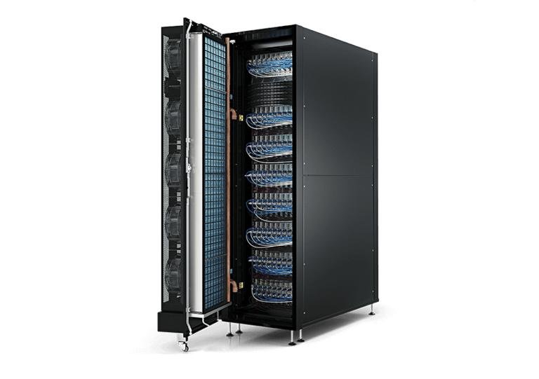
5. Specify Coolant Quality, Materials, and Leak Protection
Coolant quality is a reliability requirement, not simply a fluid procurement decision. Incompatible fluid chemistry or wetted materials can lead to corrosion, deposits, contamination, leakage, or reduced heat-transfer performance.
Confirm coolant compatibility
The selected coolant must be compatible with:
Cold plate materials
Manifolds and piping
Hoses and seals
Quick-disconnect fittings
CDU heat exchanger materials
Pumps, valves, and filters
Any additives used for corrosion control or biological management
Water-based, glycol-based, and dielectric fluids have different thermal properties and compatibility requirements. They are not interchangeable without checking equipment specifications and fluid-management procedures.
For water-based systems, the required water chemistry and treatment approach should follow the IT equipment and cooling-system manufacturers’ requirements. Filtration, corrosion control, and monitoring should be defined as part of the system design.
The Open Compute Project’s Cooling Environments work includes technical guidance and specifications covering cold plates, CDUs, connectors, manifolds, coolant fluids, and liquid-cooling integration. These resources can help project teams evaluate interfaces and compatibility, but the selected IT and facility equipment documentation remains essential.
Build leak detection and serviceability into the design
Liquid cooling introduces additional maintenance and operational requirements compared with conventional air cooling.
Recommended design considerations include:
Leak detection in relevant rack, row, and equipment locations
Isolation valves and defined shutdown procedures
Accessible connectors and service points
Suitable drip management where required
Clearly identified supply and return lines
Pressure and temperature monitoring
Procedures for filling, purging, draining, and replacing components
Spare parts and maintenance access
Leak detection should be integrated with the facility monitoring and alarm strategy. The response to an alarm should be defined before the system enters operation.
6. Design Heat Rejection and Facility Infrastructure
Removing heat from an HPC rack is only one part of the cooling process. The facility must ultimately reject that heat to the outdoor environment or another useful heat sink.
The heat-rejection system may include chillers, dry coolers, cooling towers, pumps, heat exchangers, and associated water or fluid distribution networks.
Match heat rejection to the cooling architecture
| Heat-rejection equipment | Typical role | Key design considerations |
|---|---|---|
| Chiller | Provides chilled water or another cooling fluid | Operating temperature, part-load performance, compressor energy, and redundancy |
| Dry cooler | Rejects heat from a closed fluid loop to outdoor air | Outdoor dry-bulb conditions, fan power, coil capacity, and fluid temperature |
| Cooling tower | Rejects heat through evaporative cooling | Water availability, water treatment, water consumption, and maintenance |
| Heat exchanger | Transfers heat between separate fluid circuits | Approach temperature, pressure drop, materials, and fouling |
| Economizer system | Uses favorable outdoor conditions to reduce mechanical cooling | Climate, operating temperatures, controls, and annual operating hours |
In suitable climates and system configurations, dry coolers or cooling towers may support waterside economization and reduce chiller operation. However, the benefit depends on outdoor conditions, the required coolant temperature, heat exchanger approach, and the operating limits of the IT equipment.
Consider warm-water cooling carefully
Some liquid-cooled HPC equipment is designed to operate with warmer coolant supply temperatures. This can expand the opportunity for heat rejection through dry coolers or other low-energy cooling methods.
However, the allowable supply temperature is determined by the IT equipment and the complete cooling system design. The CDU heat exchanger approach, facility water conditions, cold plate performance, and required component temperatures all matter.
Do not specify a warm-water operating target solely to avoid using a chiller. Confirm the IT equipment’s approved coolant conditions and validate the complete heat-transfer path.
Plan for redundancy and maintenance
HPC clusters may support research, commercial workloads, or critical production services. Cooling-system availability should reflect the operational consequences of equipment failure.
Design decisions may include:
N, N+1, or 2N capacity arrangements
Redundant pumps and critical components
Isolation of individual CDUs or cooling branches
Maintenance without shutting down an entire cluster, where required
Backup power for essential cooling controls and equipment
Defined response to loss of flow, high temperature, or leakage
Redundancy must be evaluated across the entire cooling chain. A redundant CDU does not provide full system resilience if both units depend on a single vulnerable pump, electrical supply, or heat-rejection path.
7. Monitoring, Commissioning, and Ongoing HPC Cooling Management
An HPC cooling system must be validated under realistic operating conditions. Equipment nameplate ratings and design calculations do not prove that the installed system can maintain the required conditions at every rack.
Monitor thermal and hydraulic performance
For air-cooled systems, monitor:
Server inlet temperatures
Rack-level temperature distribution
Supply and return air temperatures
Fan speed and operating status
Airflow and pressure conditions
Cooling-unit alarms
For liquid-cooled systems, also monitor:
Coolant supply and return temperatures
Flow rate at relevant distribution points
Differential pressure
Pump speed and power
CDU operating status
Filter condition or differential pressure, where monitored
Leak detection signals
Coolant quality indicators required by the system design
Monitoring should provide enough detail to identify a problem at the rack, row, or equipment level rather than relying only on room averages.
Commission the system under representative loads
A practical commissioning process should verify:
Equipment installation, piping, and electrical connections.
Coolant type, filling, flushing, and water-quality requirements.
Flow rate, pressure, and temperature at design operating points.
CDU heat-transfer performance under representative conditions.
Airflow and residual room cooling requirements.
Control sequences, alarms, and interlocks.
Redundancy and equipment-failure response.
Leak detection and isolation procedures.
Rack inlet or component temperature conditions under representative HPC workloads.
Where full IT load is not available during commissioning, the project team should define an appropriate load-testing and acceptance approach. The test method should reflect the system’s actual operating requirements.
Conclusion
HPC data center cooling requirements are driven by rack power density, component heat loads, server cooling interfaces, environmental limits, and the facility’s ability to reject heat reliably.
For conventional air-cooled clusters, effective airflow management and properly selected CRAC, CRAH, or in-row systems may be sufficient. For high-density GPU and accelerator deployments, direct-to-chip liquid cooling, rear-door heat exchangers, or hybrid configurations may provide a more practical way to manage concentrated heat loads.
A reliable design must go beyond nominal cooling capacity. It should verify coolant flow, pressure drop, CDU performance, fluid compatibility, condensation protection, heat rejection, redundancy, and monitoring.
Planning an HPC or GPU data center project? Contact our team to discuss your rack power density, cooling architecture, facility water conditions, and heat-rejection requirements. These details provide the starting point for evaluating suitable precision air cooling, liquid cooling, CDU, chiller, and dry-cooler configurations.
3. Frequently Asked Questions
1. What are the main cooling requirements for an HPC data center?
The main requirements include sufficient heat-removal capacity, stable server inlet temperatures, adequate airflow or coolant flow, reliable heat rejection, appropriate humidity control, and system redundancy. High-density GPU deployments also require careful evaluation of liquid-cooling interfaces, CDU capacity, and facility water conditions.
2. Is liquid cooling necessary for high-performance computing?
Not every HPC system requires liquid cooling. Air cooling may be sufficient for lower-density clusters and servers designed for conventional airflow. Direct-to-chip cooling, rear-door heat exchangers, or hybrid systems become more relevant when rack-level heat loads exceed the practical capabilities of the selected air-cooling architecture.
3. What is the difference between direct-to-chip cooling and immersion cooling?
Direct-to-chip cooling transfers heat from selected processors through cold plates and circulating coolant. Immersion cooling places compatible IT equipment directly into dielectric fluid. The two approaches have different hardware requirements, fluid-management procedures, maintenance arrangements, and integration considerations.
4. How do I calculate the coolant flow rate for an HPC liquid cooling system?
For a single-phase liquid loop, use:
For water-like fluids, an approximate volumetric flow calculation is:
The actual calculation must use the selected coolant properties and account for equipment flow limits, pressure drop, and operating conditions.
5. What should I consider when selecting a CDU for HPC?
Evaluate thermal capacity, IT-side and facility-side temperatures, flow rates, pressure drop, heat exchanger approach, pump configuration, redundancy, coolant compatibility, filtration, monitoring, and maintenance access. The CDU must be compatible with the complete liquid distribution system and IT equipment.
6. Can a dry cooler replace a chiller in an HPC data center?
In some applications, yes. If the IT equipment and liquid-cooling system can operate with coolant temperatures achievable under local outdoor conditions, a dry cooler may provide heat rejection without continuous mechanical refrigeration. However, climate, heat exchanger approach, peak ambient temperature, and equipment operating limits determine whether this is practical. A hybrid arrangement may be necessary.