Plate heat exchanger cleaning is the process of removing scale, biofilm, and deposits from plate surfaces to restore heat transfer and reduce pressure drop. The two main methods are clean-in-place (CIP) circulation for light to moderate fouling and manual cleaning with the plate pack opened for heavy or insoluble deposits. The most common causes of damage during cleaning are the wrong chemical, too high a concentration, too high a temperature, and over-tightening the plate pack on reassembly. This guide explains how to identify the fouling type, select the correct cleaning method and chemical, run a safe CIP cycle, open and clean a gasketed plate pack, replace gaskets, verify performance recovery, and avoid the mistakes that turn a routine cleaning into a plate replacement.
Quick Answer: Identify the deposit first (scale, biofilm, organic, or mixed), then select the method. Use CIP with a 1–3% chloride-free alkaline or acid solution at 40–60 °C for light fouling. Open the plate pack for hard scale or blocked channels. Rinse with chloride-free water, neutralize, and always reassemble to the marked plate pack dimension. Never exceed the gasket temperature limit.
Table of Contents
What Is Plate Heat Exchanger Cleaning and Why It Matters
How to Know When a Plate Heat Exchanger Needs Cleaning
CIP vs Manual Cleaning: Which Method Should You Use?
Fouling Types and How to Identify Them
Cleaning Chemicals: Selection, Concentration, and Temperature Limits
Step-by-Step: CIP Cleaning Procedure
Step-by-Step: Opening and Manually Cleaning a Gasketed Plate Pack
Brazed and Welded Plate Units: What You Can and Cannot Do
How to Verify Cleaning Was Successful
Plate Heat Exchanger Cleaning Checklist
Common Mistakes in Plate Heat Exchanger Cleaning
FAQ
Key Takeaways
What Is Plate Heat Exchanger Cleaning and Why It Matters
Plate heat exchanger cleaning is the removal of deposits from plate surfaces and channels to restore the original heat transfer coefficient and pressure drop. It matters because a fouled plate pack loses capacity before it fails, and the degradation is measurable.
A plate heat exchanger has narrow channels, typically 2–5 mm, with high turbulence and high surface area per volume. That design gives excellent heat transfer, but it also means:
Fouling blocks flow faster. A 1 mm deposit in a 3 mm channel removes one third of the flow area.
Pressure drop rises sharply. Pressure drop is roughly proportional to the square of velocity, so a small blockage causes a large increase.
Temperature approach widens. When the approach temperature grows, the unit can no longer reach the required outlet temperature, and downstream equipment compensates at higher energy cost.
Why Cleaning Beats Replacement
| Factor | Cleaning | Replacement |
|---|---|---|
| Cost | Chemical, labor, downtime | New plates, gaskets, or a full unit |
| Lead time | Days | 1–4 weeks for parts, 4–12 weeks for a new unit |
| Performance | Restores design duty if plates are undamaged | New design point |
| Risk | Plate or gasket damage if done wrong | Installation and piping modification risk |
| Environment | Chemical disposal and water use | Embedded carbon in new materials |
Cleaning is the correct first action when plate thickness, gasket condition, and frame integrity are still within specification. Replacement is the correct action when plates are perforated, gaskets cannot be sealed, or repeated cleaning no longer restores performance.
How to Know When a Plate Heat Exchanger Needs Cleaning
A plate heat exchanger needs cleaning when pressure drop rises 10–15% above the clean baseline, or when the temperature approach increases by 2–3 °C. These are condition-based triggers, not calendar dates, and they apply to both gasketed and brazed units.
The Three Monitoring Values
Heat duty:
Q = m × cp × ΔTWhere Q = heat duty (kW), m = mass flow rate (kg/s), cp = specific heat (kJ/kg·K), ΔT = temperature change (K).
Log mean temperature difference:
LMTD = (ΔT1 − ΔT2) / ln(ΔT1 / ΔT2)Overall heat transfer coefficient:
U = Q / (A × LMTD)Where U = overall heat transfer coefficient (W/m²·K), A = effective plate area (m²).
As fouling develops, U falls and the required area for the same duty rises. Tracking U against the clean baseline gives the most reliable cleaning trigger.
Symptom-to-Cause Table
| Symptom | Likely Cause | Action |
|---|---|---|
| Pressure drop up 10–15% | Light fouling or debris | CIP cleaning |
| Pressure drop up more than 25% | Heavy scale or blocked channels | Open plate pack and clean manually |
| Outlet temperature below setpoint | Fouling, low flow, or air | Verify flow and vents, then clean |
| Approach temperature growing | Fouling or plate damage | Clean, then inspect plates |
| Leak at gasket edge | Gasket aging or overpressure | Reduce pressure, inspect gaskets |
| Uneven temperature across the pack | Channel blockage or plate misalignment | Open and inspect |
Cleaning Frequency by Application
| Application | Typical Cleaning Interval | Dominant Fouling Type |
|---|---|---|
| HVAC chilled water / condenser | 12–24 months | Scale, biofilm |
| District heating | 12–24 months | Scale, iron oxide |
| Refrigeration condenser | 6–12 months | Scale, oil |
| Food and dairy | Daily to weekly (CIP integrated) | Protein, fat, mineral |
| Chemical process | 3–12 months | Process-specific deposits |
| Marine seawater cooling | 3–6 months | Biofilm, scale, corrosion products |
| Data center cooling | 12–24 months | Biofilm, scale |
| Hydrogen and energy storage cooling | 12–24 months | Glycol degradation products, scale |
CIP vs Manual Cleaning: Which Method Should You Use?
CIP is better for light to moderate fouling that dissolves in chemical solution, while manual cleaning is better for hard scale, blocked channels, and deposits that chemicals cannot remove. The decision depends on deposit type and how much the pressure drop has risen.
Comparison Table
| Criterion | CIP Cleaning | Manual Cleaning (Opened Pack) |
|---|---|---|
| Deposit type | Scale, biofilm, soluble organics | Hard scale, debris, fibrous material |
| Downtime | 2–6 hours | 6–24 hours |
| Gasket risk | Low (no disassembly) | Moderate (disassembly and reassembly) |
| Plate risk | Low | Moderate (handling damage) |
| Chemical use | Higher volume, lower concentration | Lower volume, higher concentration |
| Labor | Low | High |
| Frequency | Routine | When CIP is insufficient |
| Recommended when | Pressure drop up 10–25% | Pressure drop up more than 25%, or CIP fails |
Decision Logic
Pressure drop up 10–15%, temperatures still acceptable → CIP.
Pressure drop up 15–25%, CIP restores baseline → continue CIP schedule.
Pressure drop up more than 25%, or CIP does not restore baseline → open the pack.
Visible leakage, cross-contamination, or plate damage suspected → open the pack regardless of pressure drop.
Fouling Types and How to Identify Them
Fouling type determines chemical selection. Identifying the deposit before cleaning prevents wasted chemicals and plate damage. Most deposits are one of four types or a mixture.
Deposit Identification Guide
| Deposit Type | Appearance | Typical Source | Removal Method |
|---|---|---|---|
| Mineral scale | White, cream, or grey hard crust | Hard water, calcium carbonate, calcium sulfate | Acid cleaning |
| Iron oxide | Brown, orange, or black film | Carbon steel corrosion, oxygen ingress | Acid with corrosion inhibitor |
| Biofilm / biological | Slimy, green, brown, or black layer | Cooling water, stagnant zones | Alkaline detergent, then sanitizer |
| Organic / oily | Greasy, dark, or waxy film | Process fluids, lubricants, food | Alkaline detergent |
| Protein / food | Pale, sticky film | Dairy, food, beverage | Alkaline, then acid rinse |
| Glycol degradation products | Dark, acidic, gummy residue | Aged glycol loops | Alkaline, sometimes with dispersant |
| Mixed | Layered or mottled appearance | Most real systems | Alkaline first, then acid |
Why Order Matters for Mixed Deposits
For mixed organic and mineral fouling, clean with alkaline first to remove organic material and expose the mineral layer, then acid to dissolve scale. Reversing the order can bake organic deposits onto the plate surface, making them harder to remove.
Cleaning Chemicals: Selection, Concentration, and Temperature Limits
The correct cleaning chemical dissolves the deposit without attacking the plate material or the gasket. For stainless steel plates, the critical rule is to use chloride-free chemicals, because chlorides cause pitting and stress corrosion cracking.
Chemical Selection Table
| Chemical Type | Typical Concentration | Typical Temperature | Target Deposit | Notes |
|---|---|---|---|---|
| Alkaline (caustic-based) | 1–3% | 50–80 °C | Organics, biofilm, protein, fat | Verify gasket temperature limit; rinse thoroughly |
| Nitric acid | 0.5–2% | 40–60 °C | Mineral scale, iron oxide | Chloride-free; commonly used on stainless |
| Sulfamic acid | 1–5% | 40–60 °C | Scale | Less aggressive than nitric on some deposits |
| Citric acid | 1–3% | 40–60 °C | Light scale, passivation | Mild; good for sensitive applications |
| Phosphoric acid | 1–3% | 40–60 °C | Scale, light oxide | Check local discharge regulations |
| Inhibited acid blends | Per supplier | Per supplier | Mixed scale and oxide | Inhibitor protects plates from acid attack |
| Dispersants / surfactants | 0.1–1% | Per supplier | Organic and particulate | Often added to alkaline or acid stages |
| Sanitizer | Per supplier | Per supplier | Microbiological | Food and pharmaceutical applications |
Gasket Temperature Limits
Exceeding the gasket temperature limit during cleaning permanently deforms the gasket and causes leakage. The cleaning temperature must stay below the limit with a safety margin.
| Gasket Material | Typical Continuous Service Limit | Suggested Maximum Cleaning Temperature |
|---|---|---|
| NBR | 110–120 °C | 80–90 °C |
| EPDM | 150 °C | 110–120 °C |
| FKM (Viton-type) | 180 °C | 140–150 °C |
| PTFE-encapsulated | 175–200 °C | 150 °C |
| Compressed fiber / graphite | Application-specific | Per supplier |
Critical Chemical Rules
Never use hydrochloric acid (HCl) on stainless steel plates. Chlorides cause pitting and stress corrosion cracking, even at low concentration.
Never use chloride-containing water for mixing or rinsing. Use demineralized or low-chloride water where possible.
Do not exceed the gasket temperature limit. Temperature accelerates chemical attack on elastomers.
Always neutralize after acid cleaning. Residual acid continues to attack plates and contaminates the process.
Check compatibility before every new chemical. Verify with the plate material, gasket material, and any brazing filler if applicable.
Dispose of cleaning solutions per local regulations. Neutralize acids before discharge.
Step-by-Step: CIP Cleaning Procedure
CIP cleaning circulates chemical solution through the plate pack without opening it. It is the fastest method and the safest for gaskets and plates when done correctly.
Isolate the unit. Close all inlet and outlet valves on both circuits. Apply lockout/tagout.
Depressurize and drain. Open drain valves and confirm zero pressure on both sides.
Connect the CIP unit. Connect to the lowest connection on one side and return from the highest connection to vent air. Repeat for the second circuit or clean sequentially.
Flush with water first. Circulate low-chloride water for 5–10 minutes to remove loose debris. Drain.
Prepare the cleaning solution. Mix at the recommended concentration in low-chloride water. Heat to the target temperature within the gasket limit.
Circulate in the correct direction. Circulate in the normal flow direction for the first pass, then reverse for the second pass to reach both sides of the flow path.
Maintain flow velocity. Aim for a velocity that produces turbulent flow in the channels. As a rule of thumb, circulate at 1.5–2 times the normal operating flow rate where the CIP pump allows, but do not exceed the plate design pressure drop.
Monitor the solution. Check concentration, temperature, and pH every 15–20 minutes. Replace the solution if the pH changes significantly.
Circulate for the required time. Typically 30–120 minutes depending on deposit thickness. Heavy scale may need multiple cycles.
Rinse with low-chloride water. Rinse until the rinse water pH is neutral and conductivity returns to near the incoming water value.
Neutralize if acid was used. Circulate a mild alkaline solution, then rinse again.
Optional passivation. For stainless steel after acid cleaning, a mild citric or nitric passivation step can restore the passive oxide layer.
Drain and dry. Remove all liquid. Do not leave stagnant water in the unit.
Restore service and record data. Log the new pressure drop and temperatures as the new baseline.
CIP Parameter Guide
| Parameter | Typical Value | Notes |
|---|---|---|
| Alkaline concentration | 1–3% | Higher for heavy organic fouling |
| Acid concentration | 0.5–2% (nitric) | Higher risks plate attack |
| Cleaning temperature | 40–80 °C | Below gasket limit with margin |
| Circulation time | 30–120 minutes | Longer for heavy scale |
| Flow velocity | Turbulent, 1.5–2× normal | Do not exceed design pressure drop |
| Rinse water | Low-chloride | Avoid tap water with high chloride |
| Final pH | Neutral (6.5–8) | Confirm before returning to service |
Step-by-Step: Opening and Manually Cleaning a Gasketed Plate Pack
Manual cleaning is required when CIP cannot restore performance. Opening the plate pack exposes the plates for inspection and removal of hard deposits.
Isolate, depressurize, and drain. Follow lockout/tagout. Confirm zero pressure and safe temperature.
Cool the unit. Do not open a hot plate pack. Thermal shock can warp plates.
Record the plate pack dimension. Measure the distance between the frame and the pressure plate. This is the reassembly target.
Mark the plates if needed. Note the position of the first plate and the chevron direction. Some technicians number the plates to preserve order.
Loosen the tie rods evenly. Loosen in a cross pattern, a few turns at a time. Do not release one rod fully before the others.
Slide the pressure plate back. Move it along the carrying bar to open the pack.
Remove plates one at a time. Handle with both hands. Do not drag plates across each other or drop them on the edges.
Inspect each plate. Check for cracks, pitting, deformation, holes, and gasket condition.
Clean the plates. Use a soft brush, nylon pad, or low-pressure water. Do not use wire brushes, abrasive pads, or high-pressure jets on thin plates.
Clean the gasket grooves. Remove deposits from the groove without scratching the plate surface.
Soak heavily fouled plates. Use the correct chemical at the correct concentration and temperature. Do not soak different materials together.
Rinse thoroughly. Remove all chemical residue.
Replace damaged gaskets. Clip-in gaskets can be replaced individually. Glued gaskets require proper adhesive and curing.
Reassemble in the correct order. Plates must alternate direction. The first plate is usually a blank or blind plate.
Close the pack and tighten. Tighten in a cross pattern to the recorded plate pack dimension. Do not exceed the marked dimension.
Pressure test. Test at the specified test pressure per applicable code.
Restore service and record new baseline. Log pressure drop and temperatures.
Plate Handling Rules
Never place plates on a hard floor without protection.
Never stack plates directly on top of each other without a separator.
Never use a metal scraper.
Never mix plates from different units or different plate patterns.
Never reuse a gasket that has hardened, cracked, or swollen.
 Brazed and Welded Plate Units: What You Can and Cannot Do
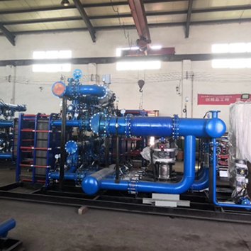 Brazed and Welded Plate Units: What You Can and Cannot Do
Brazed plate heat exchangers can only be cleaned by chemical CIP, while welded and semi-welded units allow limited cleaning depending on construction. Brazed units are sealed with copper or nickel brazing filler, so they cannot be opened or mechanically cleaned.
What You Can Do
| Unit Type | CIP Cleaning | Manual Cleaning | Plate Replacement | Gasket Replacement |
|---|---|---|---|---|
| Gasketed plate | Yes | Yes | Yes | Yes |
| Brazed plate | Yes (CIP only) | No | No | No |
| Welded plate (all-welded) | Yes (limited) | No | No | No |
| Semi-welded plate | Yes | Limited (gasketed side) | Cassette replacement | Yes (gasketed side) |
Cleaning Limits for Brazed Units
Use only chemicals compatible with copper or nickel brazing filler.
Avoid ammonia and ammonium compounds on copper-brazed units.
Keep temperature below the brazing filler and gasket limits.
If CIP does not restore performance, the unit must be replaced.
Track pressure drop trends carefully; brazed units give less warning before failure.
When to Replace a Brazed Unit
Pressure drop remains high after two CIP cycles.
Duty cannot be met after cleaning.
External corrosion or leakage is visible.
The unit has been operated outside its pressure or temperature envelope.
How to Verify Cleaning Was Successful
Cleaning is successful when pressure drop and temperature approach return to the clean baseline, or close to it. Use the same measurements you used to trigger cleaning.
Verification Table
| Check | Before Cleaning | After Cleaning | Pass Criteria |
|---|---|---|---|
| Pressure drop, side 1 | Elevated | Reduced | Within 10% of baseline |
| Pressure drop, side 2 | Elevated | Reduced | Within 10% of baseline |
| Outlet temperature | Below setpoint | At setpoint | Meets process requirement |
| Temperature approach | Wide | Narrow | Within 2 °C of baseline |
| Calculated U-value | Low | Restored | Within 10% of design |
| Visual inspection | Fouled | Clean | No visible deposits or damage |
| Leak test | N/A | Passed | No leakage at test pressure |
If Performance Does Not Recover
Pressure drop still high: Residual scale, blocked channels, or plate misalignment on reassembly.
Duty still low: Plate damage, incorrect plate count, wrong plate pattern, or gaskets bypassing flow.
Leak after reassembly: Gasket not seated, plate pack dimension incorrect, or damaged gasket.
Repeated fouling: Review water treatment, filtration, flow velocity, and operating temperature.
Plate Heat Exchanger Cleaning Checklist
Before Cleaning
- □
Confirm pressure drop and temperature baseline values
- □
Identify the fouling type
- □
Select the correct cleaning method (CIP or manual)
- □
Select the correct chemical and concentration
- □
Confirm gasket temperature limit
- □
Confirm plate and gasket material compatibility with the chemical
- □
Prepare low-chloride rinse water
- □
Isolate, depressurize, drain, and cool the unit
During CIP
- □
Flush loose debris before chemical circulation
- □
Heat solution within gasket limit
- □
Circulate in both directions
- □
Monitor concentration, temperature, and pH
- □
Rinse until neutral
- □
Neutralize acid if used
- □
Drain completely
During Manual Cleaning
- □
Record plate pack dimension before loosening
- □
Loosen tie rods evenly in a cross pattern
- □
Handle plates with both hands; do not drag or drop
- □
Inspect every plate for cracks, pitting, and deformation
- □
Replace damaged gaskets
- □
Reassemble with correct plate orientation
- □
Tighten to the recorded plate pack dimension
- □
Pressure test before returning to service
After Cleaning
- □
Record new pressure drop and temperatures
- □
Compare to baseline
- □
Document chemical used, concentration, temperature, and time
- □
Document parts replaced
- □
Review future cleaning interval based on fouling rate
- □
Dispose of chemicals per local regulations
Common Mistakes in Plate Heat Exchanger Cleaning
1. Using hydrochloric acid on stainless steel plates.
Chlorides cause pitting and stress corrosion cracking. Use chloride-free acid such as nitric, sulfamic, or citric.
2. Rinsing with high-chloride tap water.
The rinse step can do the damage the cleaning step avoided. Use low-chloride or demineralized water.
3. Exceeding the gasket temperature limit.
High cleaning temperature permanently deforms gaskets. Stay below the limit with a margin.
4. Cleaning with the wrong chemical order.
Acid before alkaline on mixed deposits can bake organic material onto the plate surface.
5. Over-tightening the plate pack on reassembly.
Tightening beyond the marked dimension crushes gaskets and deforms plates. Tighten to the dimension, not to a torque value alone.
6. Loosening one tie rod fully before the others.
This warps the pressure plate and can damage plates. Loosen in a cross pattern, a few turns at a time.
7. Reusing hardened or swollen gaskets.
A gasket that has lost elasticity will leak. Replace it during the cleaning window.
8. Mixing plates from different units.
Plates are matched to a specific pattern and plate count. Mixing them causes leakage and poor performance.
9. Using wire brushes or abrasive pads.
These scratch the plate surface and create sites for future fouling and corrosion.
10. Cleaning only one circuit.
Both sides foul. Clean both and verify both pressure drops.
11. Skipping the neutralization step.
Residual acid continues to attack plates and contaminates the process.
12. Not recording the new baseline.
Without post-cleaning data, the next cleaning trigger cannot be set accurately.
13. Assuming CIP will fix everything.
CIP cannot remove hard scale or debris. If pressure drop does not recover, open the pack.
14. Ignoring repeated fouling.
If cleaning is needed more often than expected, the problem is upstream: water treatment, filtration, flow velocity, or temperature.
FAQ
Q1: How do I clean a plate heat exchanger?
Choose CIP for light to moderate fouling and manual cleaning with the plate pack opened for heavy or insoluble deposits. Use chloride-free chemicals at the correct concentration and temperature, rinse thoroughly, neutralize, and reassemble to the marked plate pack dimension.
Q2: What chemical is used to clean a plate heat exchanger?
Alkaline detergents (1–3%) remove organic deposits and biofilm. Chloride-free acids such as nitric (0.5–2%), sulfamic (1–5%), or citric (1–3%) remove mineral scale and iron oxide. Always verify compatibility with the plate and gasket material.
Q3: Can I use hydrochloric acid to clean a plate heat exchanger?
No. Hydrochloric acid contains chlorides that cause pitting and stress corrosion cracking in stainless steel plates. Use chloride-free acids instead.
Q4: How often should a plate heat exchanger be cleaned?
Clean on condition, not on a fixed calendar. A pressure drop rise of 10–15% above baseline or a temperature approach increase of 2–3 °C is a reliable trigger. In clean service this may be every 12–24 months; in severe fouling service, every 3–6 months.
Q5: Can a brazed plate heat exchanger be cleaned?
Yes, but only by chemical CIP. Brazed units cannot be opened, so mechanical cleaning is not possible. If CIP does not restore performance, the unit must be replaced.
Q6: How long does plate heat exchanger cleaning take?
CIP typically takes 2–6 hours including rinsing and neutralization. Opening and manually cleaning a gasketed plate pack typically takes 6–24 hours depending on plate count and fouling severity.
Q7: What is the correct plate pack dimension after reassembly?
The dimension marked on the frame or recorded before disassembly. Tighten to that dimension, not to a torque value alone. Over-tightening crushes gaskets and deforms plates.
Q8: How do I know if cleaning worked?
Pressure drop should return to within 10% of the clean baseline, outlet temperature should meet setpoint, and the calculated U-value should recover to within 10% of design.
Q9: Why does my plate heat exchanger foul so quickly?
Common causes are inadequate water treatment, high operating temperature, low flow velocity, suspended solids without filtration, and excessive oversizing. Review these before increasing cleaning frequency.
Q10: Can I clean a plate heat exchanger without opening it?
Yes, with CIP circulation. CIP works for scale, biofilm, and soluble organics. It does not remove hard scale, debris, or fibrous material. If CIP fails to restore performance, the pack must be opened.
Q11: What is the cost of plate heat exchanger cleaning?
CIP cleaning cost is mainly chemicals, water, labor, and downtime. Manual cleaning costs more in labor and gasket replacement. Emergency cleaning and lost production are far more expensive than planned maintenance.
Q12: How do I dispose of cleaning chemicals?
Neutralize acids to pH 6–9 before discharge and follow local regulations. Do not discharge concentrated chemicals to drains or surface water.
Key Takeaways
Identify the deposit before choosing a chemical. Scale needs acid; organics and biofilm need alkaline.
Never use chloride-containing chemicals or rinse water on stainless steel plates. Chlorides cause pitting and stress corrosion cracking.
Stay below the gasket temperature limit. NBR, EPDM, and FKM have different limits; exceeding them permanently damages gaskets.
Use CIP for light to moderate fouling and open the pack for heavy or insoluble deposits.
Tighten the plate pack to the marked dimension, not to a torque value alone.
Verify performance after cleaning. Pressure drop within 10% of baseline and approach temperature within 2 °C indicate success.
Replace gaskets that are hardened, cracked, or swollen during the cleaning window.
If cleaning is needed too often, fix the root cause. Review water treatment, filtration, flow velocity, and operating temperature.