A data center cooling system designed only for today’s IT load can become a major constraint as computing demand increases. New server deployments, higher rack power density, GPU infrastructure, and changing cooling technologies can quickly exceed the capacity of existing cooling equipment.
Building scalable data center cooling infrastructure means designing the cooling architecture so that capacity, distribution, heat rejection, and control systems can expand without requiring a complete redesign of the facility.
The challenge is not simply installing larger chillers or adding more precision air conditioners. A scalable system must coordinate cooling capacity, rack-level heat removal, piping, electrical supply, equipment redundancy, physical space, and future liquid cooling requirements.
For data center owners, facility managers, MEP engineers, and EPC contractors, the objective is to support phased growth while maintaining thermal stability, operational reliability, and manageable lifecycle costs.
This guide explains how to plan, design, and expand cooling infrastructure for growing data centers.
1. Start with a Long-Term Cooling Capacity Plan
The first step in building scalable data center cooling infrastructure is understanding how the facility’s cooling demand will change over time.
A common planning mistake is to size the entire cooling system around the initial IT load without considering future server deployment or changes in rack density.
A better approach is to develop a phased cooling capacity plan.
A. Calculate the Current Cooling Load
The cooling system must remove the heat generated by IT equipment and other sources within the conditioned environment.
A preliminary cooling-load calculation can be expressed as:
Where:
\(Q_{\text{total}}\) = total cooling load.
\(Q_{\text{IT}}\) = heat generated by servers, storage, and networking equipment.
\(Q_{\text{electrical}}\) = heat from electrical equipment located within the conditioned space.
\(Q_{\text{lighting}}\) = heat from lighting and occupants.
\(Q_{\text{envelope}}\) = heat transfer through walls, roofs, floors, and other building elements.
\(Q_{\text{ventilation}}\) = heat introduced through outdoor air and ventilation.
IT electrical consumption largely becomes heat, so the IT load is usually the main component of a data center’s cooling requirement.
However, the total cooling load should not be treated as identical to the installed cooling capacity. Engineers must also account for equipment performance at actual operating conditions, redundancy, load distribution, and the required operating margin.
B. Plan for Future IT Load Growth
A scalable design should distinguish between:
Initial IT load.
Planned near-term expansion.
Long-term target capacity.
Maximum expected rack power density.
Future liquid cooling requirements.
For example, a facility may initially operate at a relatively low IT load but plan to deploy additional server racks in phases.
Rather than installing all cooling equipment immediately, the operator may choose modular equipment that can be added as demand increases.
The important requirement is that the initial infrastructure must support the planned expansion.
This means checking whether future equipment can be connected to the existing:
Electrical distribution.
Chilled-water or coolant piping.
Heat-rejection infrastructure.
Cooling distribution systems.
Monitoring and control networks.
Equipment rooms and outdoor installation areas.
C. Plan at Both Facility and Rack Levels
Total facility IT load does not tell the complete story.
Two data centers with the same IT capacity can have very different cooling requirements if their rack power densities are different.
For example:
A facility with evenly distributed rack loads may be suitable for conventional room-level air cooling.
A facility with concentrated high-density GPU racks may require in-row cooling, rear-door heat exchangers, or direct-to-chip liquid cooling.
Scalable cooling infrastructure must therefore account for both total facility capacity and the thermal requirements of individual racks.
2. Choose a Cooling Architecture That Supports Expansion
The cooling architecture determines how heat is collected, transferred, distributed, and rejected.
A scalable design should avoid unnecessary dependence on a single cooling method, particularly when future rack density and IT equipment requirements are uncertain.
A. Precision Air Cooling Infrastructure
Precision air cooling remains an important part of many data center cooling architectures.
Common equipment includes:
Precision air conditioners.
Computer Room Air Conditioners (CRACs).
Computer Room Air Handlers (CRAHs).
In-row cooling systems.
Rear-door heat exchangers.
Cold aisle containment systems.
These technologies serve different purposes.
CRAC units commonly use direct-expansion refrigeration, while CRAH units typically use chilled-water coils connected to an external cooling plant.
In-row cooling places cooling equipment close to the server racks, reducing the distance between heat generation and heat removal.
Rear-door heat exchangers remove heat from server exhaust air through a heat exchanger mounted on or integrated with the rack door.
Cold aisle containment helps control airflow and reduce mixing between cold supply air and hot exhaust air.
How to make air cooling scalable:
Design chilled-water or refrigerant distribution with planned expansion points.
Reserve physical space for additional precision cooling equipment.
Use containment to improve airflow management as rack populations grow.
Evaluate rack-level cooling requirements before increasing server density.
Ensure pumps, piping, electrical distribution, and controls can support additional units.
Room-level air cooling may remain suitable for many facilities, but it should not be assumed that adding more CRAC or CRAH units will solve every high-density cooling problem.
B. Modular Chiller and Heat-Rejection Infrastructure

Chillers and heat-rejection equipment are central to many scalable cooling systems.
Depending on the project, the cooling plant may use:
Air-cooled chillers.
Water-cooled chillers.
Dry coolers.
Cooling towers.
Plate heat exchangers.
Chilled-water pumps.
Condenser-water pumps.
A modular plant can be expanded by adding equipment as IT demand increases.
For example, instead of installing the entire planned cooling capacity during the first construction phase, the operator can deploy an initial group of chillers and reserve space, piping connections, electrical capacity, and control interfaces for future units.
However, modular equipment does not automatically create a scalable system.
The supporting infrastructure must also be designed for the final planned capacity.
This includes:
Main pipe sizing.
Pump capacity and operating ranges.
Header arrangements.
Electrical switchgear.
Heat-rejection capacity.
Control system architecture.
Isolation valves and maintenance access.
If the main chilled-water header or electrical supply is undersized, adding another chiller may not increase usable cooling capacity.
C. Hybrid Air and Liquid Cooling Infrastructure

Growing data centers may need to support traditional servers and high-density GPU infrastructure within the same facility.
A hybrid architecture can combine:
Room-level precision air conditioning.
In-row cooling.
Rear-door heat exchangers.
Direct-to-chip liquid cooling.
Coolant Distribution Units (CDUs).
Central chilled-water or heat-rejection systems.
Direct-to-chip liquid cooling transfers heat from selected components, such as CPUs and GPUs, through cold plates and a circulating coolant loop.
It does not necessarily remove all heat from the rack. Power supplies, memory, storage, networking components, and other equipment may still reject heat into the surrounding air, depending on the server design.
For this reason, a facility using direct-to-chip cooling may still need air-side cooling infrastructure.
The central cooling plant must also be compatible with the liquid cooling system’s required temperatures, flow rates, pressure conditions, and heat-exchange interfaces.
3. Design Modular Capacity and Redundancy Together
Modular capacity planning allows cooling infrastructure to grow in stages. Redundancy ensures that the cooling system can continue operating when equipment fails or requires maintenance.
These two requirements should be considered together.
A. Understand N, N+1, and 2N Cooling Redundancy
Common cooling redundancy configurations include:
Configuration | Description | Main consideration |
|---|---|---|
N | Installed capacity meets the required cooling load | No additional capacity for a single equipment failure |
N+1 | One additional capacity unit beyond the required load | Can provide equipment-level redundancy if the remaining system has sufficient capacity |
2N | Two independent systems, each designed to support the required load | Higher infrastructure cost and more complex integration |
The actual resilience depends on the complete cooling path, not just the number of chillers or precision cooling units.
For example, a data center may have N+1 chillers but still have a single point of failure in:
Main chilled-water headers.
Pump power supplies.
Control panels.
Cooling distribution valves.
Heat-rejection equipment.
Electrical switchgear.
A redundancy review should identify shared components and determine whether they undermine the intended availability level.
B. Expand Cooling Capacity Without Disrupting Operations
Growing data centers often need to install additional equipment while existing IT systems remain operational.
This makes isolation and maintenance planning essential.
Useful design considerations include:
Isolation valves around major equipment.
Separate pump and equipment connections where appropriate.
Space for future chillers and cooling units.
Accessible piping and electrical routes.
Control sequences for equipment staging.
Commissioning procedures for new modules.
The objective is to allow new equipment to be integrated without unnecessarily interrupting existing cooling services.
C. Avoid Excessive Oversizing
Installing all future cooling capacity at the beginning may appear to provide flexibility, but oversized equipment can operate inefficiently at low loads.
Potential problems include:
Poor part-load performance.
Unnecessary initial capital expenditure.
Higher minimum flow requirements.
Unfavorable equipment staging.
Increased maintenance burden.
A phased modular approach can be more practical, provided the supporting infrastructure is designed correctly.
4. Build Scalable Cooling Distribution and Liquid Cooling Interfaces
Cooling generation is only one part of the system.
Even if a chiller has sufficient capacity, the facility may experience overheating if chilled water or coolant cannot be delivered to the required locations at the correct temperature and flow rate.
A. Design Chilled-Water Distribution for Future Loads
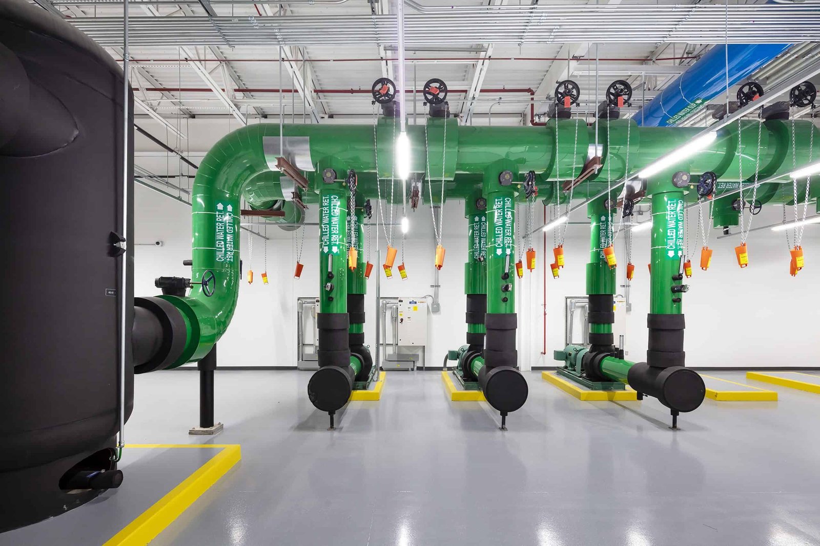
A scalable chilled-water system should consider:
Main supply and return pipe sizing.
Pump capacity and control.
Hydraulic balancing.
Pressure drop.
Isolation and bypass arrangements.
Future connection points.
Water treatment and filtration.
Temperature and flow monitoring.
Piping should be designed around the expected final load and the operating requirements of the equipment.
An undersized main pipe can restrict flow and increase pressure drop as the facility expands.
Similarly, a pump selected only for the initial operating phase may not support the required future flow rate.
Variable-speed pumps can help match water flow to changing cooling demand, provided the system is designed with suitable control valves, sensors, and minimum flow requirements.
B. Prepare for Direct-to-Chip Liquid Cooling
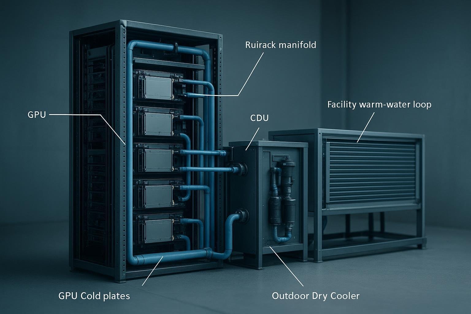
Liquid cooling introduces additional infrastructure requirements that should be considered before high-density racks are installed.
A typical direct-to-chip arrangement may include:
Cold plates.
Rack manifolds.
Coolant distribution units.
Facility water connections.
Secondary coolant loops.
Pumps and control valves.
Leak detection.
Temperature, flow, and pressure sensors.
CDU configurations vary. Some systems use liquid-to-liquid heat exchangers to separate the technology cooling loop from the facility water loop, while other arrangements use different heat-transfer or pumping configurations.
Before selecting a CDU, engineers should confirm:
Required cooling capacity.
Primary and secondary fluid conditions.
Supply and return temperatures.
Flow-rate requirements.
Pressure-drop limits.
Coolant compatibility.
Connection types and dimensions.
Monitoring and control interfaces.
Leak detection and maintenance requirements.
The facility should also reserve space for piping routes, manifolds, CDU installation, service access, and future rack connections.
C. Maintain Air-Side Cooling for Residual Heat
Liquid cooling does not necessarily eliminate the need for room-level air conditioning.
Some components remain air-cooled, and the facility also has electrical and environmental heat gains.
A scalable design should therefore calculate the residual air-side load after liquid cooling is introduced.
This avoids two common mistakes:
Assuming that liquid cooling removes all rack heat.
Retaining an air-cooling system sized without considering the changed heat distribution.
The air-side and liquid-side systems should be designed as coordinated parts of the same thermal architecture.
5. Use Monitoring and Intelligent Controls to Manage Growth
As cooling infrastructure becomes larger and more distributed, monitoring and control become increasingly important.
A system that works reliably at a small scale may become difficult to manage when additional chillers, pumps, cooling units, and liquid cooling circuits are added.
A. Monitor Cooling Performance at Multiple Levels
A scalable monitoring strategy should cover the central cooling plant, distribution network, and IT environment.
Central plant monitoring:
Chiller operating status.
Supply and return water temperatures.
Pump speed and power.
Flow rates.
Pressure differences.
Cooling-tower or dry-cooler performance.
Equipment alarms.
Room and rack monitoring:
Rack inlet temperatures.
Supply and return air temperatures.
Humidity and dew point.
Hot-spot detection.
Cooling-unit operating status.
Airflow conditions.
Liquid cooling monitoring:
Coolant supply and return temperatures.
Flow rate.
Pressure.
Differential pressure.
Leak detection.
CDU alarms and operating status.
The exact monitoring points should be determined by the cooling architecture and equipment requirements.
B. Use Controls to Match Capacity with Demand
As IT load changes, the cooling system should adjust equipment operation accordingly.
A control strategy may include:
Automatic chiller staging.
Pump speed adjustment.
Fan speed control.
Cooling-unit sequencing.
Supply-water temperature control.
Alarm thresholds.
Equipment isolation and failure response.
The goal is to avoid operating unnecessary equipment while maintaining sufficient cooling capacity and redundancy.
Control logic should also prevent unstable operation when new cooling modules are introduced.
For example, adding a new chiller without updating pump sequencing, flow control, and system staging can create operating problems even when the equipment itself is correctly sized.
C. Commission Each Expansion Phase
Every new module should be tested before it is relied upon for critical cooling.
Commissioning should verify:
Design flow rates.
Supply and return temperatures.
Equipment capacity under actual conditions.
Control sequences.
Alarm functions.
Failure response.
Redundancy behavior.
Integration with existing monitoring systems.
Where practical, testing should include different operating conditions and equipment failure scenarios.
Commissioning should also update system documentation, control diagrams, and maintenance procedures.
6. Control Lifecycle Cost and Prepare for Future Expansion
Scalable infrastructure should support growth without creating unnecessary capital expenditure or excessive operating costs.
A cooling system should therefore be evaluated over its expected operating life, not only by initial equipment price.
A. Compare Capital and Operating Costs
A lifecycle-cost assessment should include:
Cost category | What to evaluate |
|---|---|
Initial equipment | Chillers, precision cooling units, pumps, dry coolers, cooling towers, CDUs |
Installation | Piping, electrical work, structural support, insulation, controls |
Energy | Chillers, pumps, fans, cooling units, auxiliary equipment |
Water | Makeup water, treatment, discharge, and applicable water charges |
Maintenance | Inspections, cleaning, consumables, labor, spare parts |
Expansion | Additional modules, connection work, system modifications |
Replacement | Expected equipment replacement and major component repairs |
The lowest initial equipment cost does not necessarily produce the lowest lifecycle cost.
For example, an equipment arrangement that requires extensive modification during each expansion phase may create higher long-term project costs.
B. Evaluate Energy Efficiency at Different Load Levels
Cooling equipment often operates at part load rather than continuously at full rated capacity.
Therefore, compare equipment performance at the expected operating conditions.
Important factors include:
Chiller part-load performance.
Pump efficiency.
Fan energy.
Cooling-water temperatures.
Heat-rejection conditions.
Equipment staging.
Control strategy.
Free-cooling opportunities where suitable.
PUE can help assess overall facility energy efficiency:
However, PUE is a facility-level metric. It does not independently measure the efficiency of an individual chiller, dry cooler, or liquid cooling system.
For equipment selection, detailed cooling-system energy analysis is more useful.
C. Reserve Physical Space and Infrastructure Capacity
A scalable cooling design must account for space as well as thermal capacity.
Reserve suitable space for:
Additional chillers.
Dry coolers or cooling towers.
Pumps and heat exchangers.
Precision cooling units.
CDUs and liquid cooling manifolds.
Piping and electrical distribution.
Maintenance access.
Future equipment replacement.
Outdoor equipment also requires consideration of airflow, noise, structural loading, service access, and heat discharge.
A facility may have enough electrical and cooling capacity on paper but still be unable to expand because there is no practical space for additional equipment or piping.
8. Frequently Asked Questions
1. What makes data center cooling infrastructure scalable?
Scalable cooling infrastructure can support increasing IT loads through planned equipment expansion, suitable piping and electrical capacity, modular cooling equipment, flexible distribution, and adaptable control systems. It should also account for redundancy and future rack density.
2. Should a data center install all cooling capacity at the beginning?
Not necessarily. A phased modular approach can reduce initial capital expenditure and avoid operating oversized equipment at low loads. However, the initial design should reserve sufficient space, piping connections, electrical capacity, and heat-rejection infrastructure for future expansion.
3. How does liquid cooling affect data center infrastructure planning?
Direct-to-chip liquid cooling requires additional components such as CDUs, manifolds, coolant piping, pumps, sensors, and leak detection. It also changes how heat is distributed between liquid and air systems. These interfaces should be planned before high-density racks are installed.
4. Can existing data center cooling systems support higher rack density?
Sometimes, but additional cooling units alone may not solve the problem. Engineers should evaluate rack inlet temperatures, airflow, chilled-water capacity, pipe flow, pressure drop, and the heat-rejection plant. High-density racks may require in-row cooling, rear-door heat exchangers, or direct-to-chip liquid cooling.
5. What cooling redundancy is suitable for a growing data center?
N, N+1, and 2N are common design approaches. The appropriate arrangement depends on the required availability, budget, maintenance strategy, and risk assessment. Redundancy should cover the complete cooling path, including pumps, power, distribution, heat rejection, and controls.
6. What information is required to design scalable cooling infrastructure?
A preliminary engineering assessment should include the data center location, current and planned IT loads, rack power density, cooling architecture, supply and return temperatures, water availability, electrical capacity, redundancy requirements, site drawings, and expansion schedule.