For process industries across North America and Europe—including oil refining, petrochemical manufacturing, power generation, and specialty chemical production—shell and tube heat exchangers are the workhorse of high-temperature, high-pressure (HTHP) thermal operations. These units handle feed preheating, product cooling, waste heat recovery, and process condensation under conditions that would quickly destroy gasketed plate, spiral plate, or other compact exchanger designs. Yet selection errors are alarmingly common: many engineering teams specify units based solely on nominal pressure and temperature ratings, overlooking material compatibility, thermal stress, corrosion allowance, and structural suitability. The result is premature tube failure, tube sheet cracking, seal leaks, and unplanned shutdowns that can cost $50,000–$250,000 per outage event in lost production and emergency repair.
Selecting the right shell and tube exchanger for HTHP service is a multi-disciplinary exercise, not a catalog selection task. It requires aligning material science, mechanical design, thermal engineering, and corrosion control with the specific demands of the application. This guide breaks down the core selection criteria, proven configuration options, compliance standards, and common pitfalls for HTHP shell and tube exchangers, aligned with ASME, TEMA, API, and EN industry standards.
Why Shell and Tube Exchangers Are the Standard for HTHP Duty
Before diving into selection details, it is important to understand why shell and tube designs dominate extreme-duty applications over alternative heat exchanger technologies:
- All-metal welded construction: No gaskets, elastomers, or adhesive seals are exposed to process conditions, eliminating the most common failure points in high-temperature service.
- Extreme pressure and temperature capability: Properly engineered units can operate at pressures up to 400+ bar and temperatures from cryogenic ranges to 1,000°C+ depending on material selection.
- Tolerance for harsh media: Handles corrosive fluids, high-fouling streams, particulate-laden process fluids, and phase-change services that would plug or erode compact exchanger designs.
- Proven compliance: Fully support ASME BPVC, TEMA, API 660, and EN 13445 design codes required for regulated industries.
- Maintainability: Removable tube bundles allow mechanical cleaning, tube replacement, and in-situ repair without full equipment removal.
For hydrocracking units, catalytic reformers, power plant boiler feedwater heaters, high-temperature waste heat boilers, and chemical synthesis reactors, there is no viable alternative to shell and tube technology for HTHP service.
Core Design Codes and Compliance Standards
HTHP heat exchangers are pressure vessels, and their design must follow recognized regional and industry standards. For North American and European markets, the following are the most common and most rigorous:
- ASME BPVC Section VIII, Division 1 & 2: The baseline pressure vessel code in the U.S. Division 2 allows higher stress factors and is required for many high-pressure refinery applications.
- TEMA Standards (TEMA R, C, B Classes): The Tubular Exchanger Manufacturers Association standard defines construction tolerances, testing requirements, and design practices specifically for shell and tube exchangers. TEMA Class R is required for most refinery and heavy petrochemical HTHP service; Class C for general chemical service; Class B for general-purpose moderate duty.
- API Standard 660: The American Petroleum Institute’s industry-specific standard for shell and tube exchangers in petroleum refining and gas processing, with stricter corrosion, fatigue, and inspection requirements.
- EN 13445: The European Union harmonized pressure vessel standard, required for CE-marked equipment installed in EU member states.
Always define the required code class before requesting quotations. Different standards use different safety factors, inspection frequencies, and material qualification requirements, which can change pricing by 30–60% for equivalent thermal performance.
Material Selection: The Foundation of HTHP Reliability
Material selection is the single most important decision for HTHP shell and tube exchangers. The wrong material will fail by corrosion, creep, or fatigue long before the end of the design life, even if pressure and temperature ratings appear adequate on paper. Selection must account for temperature, pressure, fluid chemistry, and expected service life.
Tube Material Options
Tubes are exposed to the most severe combination of temperature, pressure, velocity, and corrosion. Choose based on the most aggressive side of the exchanger:
- Carbon steel (SA-179, SA-106 Grade B): The baseline for non-corrosive, clean service. Suitable for continuous temperatures up to ~425°C and moderate pressures. Low cost, widely available, and easily welded. Not suitable for acidic, sulfidic, or high-chloride fluids.
- Low-alloy Cr-Mo steels (SA-335 P11, P22, P91): The industry standard for refinery HTHP service. 1.25Cr-0.5Mo (P11) is rated to ~550°C; 2.25Cr-1Mo (P22) to ~590°C; 9Cr-1Mo (P91) to ~650°C. Excellent resistance to hydrogen attack, sulfidation, and high-temperature creep. Used extensively in hydrotreaters, reformers, and crude unit preheaters.
- Austenitic stainless steels (304/304L, 316/316L): Suitable for temperatures up to ~600°C with good general corrosion resistance. Low-carbon “L” grades are required for HTHP service to prevent intergranular corrosion from weld sensitization. 316L is preferred for chloride-containing or mildly acidic process fluids.
- Duplex stainless steels (2205, 2507): Combine high tensile strength with excellent pitting and crevice corrosion resistance. Ideal for medium-temperature, high-pressure applications with chlorides or sour gas.
- Nickel-base alloys (Inconel 600/625, Hastelloy C276): The premium choice for extreme HTHP corrosive service. Inconel 625 handles temperatures up to 870°C with outstanding sulfidation and oxidation resistance. Hastelloy C276 provides superior resistance to strong acids and chlorides at elevated temperatures. Used for the most severe chemical process and waste heat boiler applications.
- Titanium and titanium alloys: Excellent corrosion resistance in chloride and seawater service at intermediate temperatures. Not recommended for temperatures above 315°C due to hydriding risk.
Tube Sheet and Shell Materials
The tube sheet is the highest-stress component in the exchanger, and material mismatch is a leading cause of premature failure.
- Matching principle: Select tube sheet material compatible with tube material to avoid galvanic corrosion. Dissimilar metal pairs with large electrode potential differences will corrode rapidly at the tube-to-tube sheet joint under HTHP conditions.
- Clad / overlay tube sheets: For corrosive service, use a carbon steel or low-alloy base tube sheet with a 3–6mm corrosion-resistant weld overlay (stainless steel, Inconel, or Hastelloy) on the process side. This delivers the strength of a thick base plate with the corrosion resistance of a premium alloy at 30–50% lower cost than solid alloy construction.
- Shell material: Typically one grade below tube material for economy, sized to match shell-side fluid conditions.
Corrosion Allowance
Never specify zero corrosion allowance for HTHP service. High temperatures accelerate corrosion rates by 2–4x compared to ambient conditions.
- Specify 1.5–3.0 mm corrosion allowance for tubes and tube sheets in mild to moderate service.
- Specify 4.0–6.0 mm for highly corrosive or high-temperature sulfidic service.
- Verify corrosion rates with the specific fluid composition and temperature; generic rules of thumb are frequently wrong for aggressive chemistries.
Configuration Selection: Match Structure to Operating Conditions
Shell and tube exchangers come in multiple mechanical configurations, each optimized for different temperature, pressure, and maintenance profiles. TEMA designations are the industry standard for defining configuration.
Fixed Tube Sheet (BEM, BFM Type)
- Design: Tube sheets are welded solidly to the shell at both ends. Simple, robust, and low cost.
- Best for: HTHP service with low tube-to-shell temperature differential (<50°C), clean non-fouling fluids, and steady continuous operation. Common for boiler feedwater heaters and clean process preheaters.
- Limitations: Cannot accommodate large thermal expansion differences; high thermal stress will crack tube sheets or pull tubes if temperature differentials are large. Tube bundle cannot be removed for cleaning or inspection.
U-Tube Bundle (BKU, BCU Type)
- Design: Tubes are bent into a U-shape, anchored only at one tube sheet. The opposite end is free to expand and contract with temperature changes.
- Best for: HTHP applications with large temperature differentials (>80°C) and frequent temperature cycling. The U-bend design naturally absorbs thermal expansion without expansion joints or floating heads. Common for feed/effluent exchangers in hydroprocessing units.
- Limitations: Inner bend of U-tubes is difficult to clean mechanically; not ideal for heavily fouling fluids. Tube-side flow must remain turbulent to prevent sediment deposition in the bends.

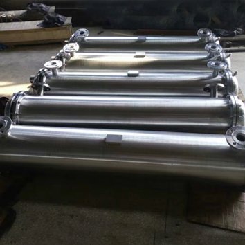
Floating Head (AES, AET Type)
- Design: One tube sheet is fixed; the other is allowed to float freely inside the shell, with a floating head cover to seal the shell side. Fully accommodates thermal expansion. Tube bundle can be pulled for inspection, cleaning, or tube replacement.
- Best for: The gold standard for severe HTHP service with large temperature swings, fouling process fluids, and high availability requirements. The most common configuration in refineries, petrochemical plants, and continuous process facilities.
- Limitations: More complex, heavier, and 30–60% more expensive than fixed tube sheet designs.
Double Tube Sheet (DTS)
- Design: Two separate tube sheets with an intermediate leak detection chamber between them. Prevents cross-contamination between tube-side and shell-side fluids.
- Best for: HTHP pharmaceutical, food-grade, or hazardous fluid service where cross-contamination would create safety or product quality risks.
Fluid Allocation Rule of Thumb
- Route high-pressure fluids through the tube side: Tube walls are thinner and more efficient for containing pressure, reducing material cost.
- Route corrosive, fouling, or high-temperature fluids through the tube side: Concentrates expensive corrosion-resistant material on the tube side only, and makes cleaning easier.
- Route low-pressure, high-flow fluids through the shell side: Minimizes pressure drop and maximizes heat transfer efficiency.
Thermal & Hydraulic Design for Long-Term Reliability
Thermal sizing alone does not guarantee reliable HTHP performance. Poor hydraulic design causes erosion, fouling, and vibration failure modes.
Flow Velocity Optimization
- Target tube-side liquid velocity of 1.5–2.5 m/s and gas velocity of 15–30 m/s for clean service.
- Reduce velocity by 10–20% for HTHP corrosive service: high velocity combined with high temperature accelerates erosion-corrosion dramatically.
- Avoid velocities below 1.0 m/s for liquids: promotes sediment deposition, fouling, and under-deposit corrosion.
Thermal Stress Management
Thermal expansion stress is the leading cause of tube sheet cracking and tube joint failure in HTHP exchangers.
- For fixed tube sheet designs with >50°C differential, add a shell-side expansion joint to absorb growth.
- For >80°C differential, specify U-tube or floating head designs instead of relying on expansion joints alone.
- Always perform creep analysis for long-term continuous operation above 425°C for carbon steel and 550°C for low-alloy steel.
Pressure Drop Control
- Limit tube-side pressure drop to 5–10% of operating pressure for high-pressure systems. Excessive drop requires larger, higher-pressure pumps and adds system cost.
- Model pressure drop at operating temperature, not ambient. Fluid viscosity changes dramatically at HTHP conditions, changing real-world hydraulics.
Fouling Allowance
- Add 15–25% excess surface area for moderate fouling service; add 30–50% for heavy fouling or coking applications.
- Specify increased tube pitch and plain tubes (not finned) for fouling-prone streams to allow access for mechanical cleaning.
Common Selection Pitfalls to Avoid
Even experienced process engineers fall into predictable traps when specifying HTHP shell and tube exchangers:
- Relying only on nominal ratings: Nominal pressure-temperature ratings are based on room temperature. Allowable stress drops significantly at elevated temperatures. Always verify design using material-specific high-temperature allowable stress values per ASME II D.1.
- Mismatched tube and tube sheet materials: Galvanic corrosion at the tube joint will cause failure 2–5x faster than uniform corrosion. Always match electrochemical potential across the joint.
- Ignoring thermal fatigue: Cyclic temperature operation (startup/shutdown, batch processes) will fatigue fixed tube sheet designs quickly. Specify U-tube or floating head for cycling duty.
- Skimping on corrosion allowance: High temperatures accelerate corrosion. What would be 10-year life at ambient can be 2–3 years at 500°C with the same allowance.
- Oversizing on heat duty alone: Excessively large units run at low velocity, causing fouling and under-deposit corrosion that negates the extra surface area. Size for both heat transfer and optimal flow velocity.
Step-by-Step Selection Process
Follow this structured approach to specify the optimal exchanger for your HTHP application:
- Define full operating conditions: Document fluid composition, inlet/outlet temperatures, design pressure, flow rates, phase state, fouling tendency, corrosion severity, and temperature cycling frequency. Include both normal operation and upset conditions.
- Define code and compliance requirements: Specify ASME/TEMA/API/EN class, inspection requirements, and material certification requirements.
- Shortlist materials and configuration: Match material to corrosion and temperature; match configuration to differential temperature and maintenance needs.
- Perform thermal and mechanical design: Calculate heat transfer area, tube count, and shell size; verify wall thickness, tube sheet thickness, and stress levels at design temperature.
- Validate hydraulics and fouling: Confirm velocity, pressure drop, and fouling margin fall within acceptable ranges.
- Evaluate total cost of ownership: Compare options on 15-year lifecycle cost including purchase, installation, maintenance, cleaning, and estimated downtime, not just upfront price.
Conclusion
High-temperature, high-pressure shell and tube heat exchanger selection is a precision engineering exercise, not a commodity purchasing decision. The difference between a properly specified unit and a catalog-specified unit is 10–20+ years of reliable service vs. 2–5 years of leaks, repairs, and unplanned shutdowns. By aligning material selection, mechanical configuration, thermal design, and corrosion control with the specific demands of the application, and following recognized industry design codes, engineering teams can deliver HTHP heat exchangers that perform reliably through decades of harsh service.